New tube plate welding method

A tube sheet welding and welding tool technology, applied in welding equipment, non-electric welding equipment, metal processing equipment, etc., can solve the problems of insufficient welding strength and materials that cannot be welded, and achieve high welding strength, small residual stress and deformation, and welding. low temperature effect

Inactive Publication Date: 2013-06-26
苏州森光换热器有限公司
View PDF5 Cites 16 Cited by
  • Summary
  • Abstract
  • Description
  • Claims
  • Application Information

AI Technical Summary

Problems solved by technology

If the friction stir welding is used to weld the pipe and plate, the welding tool should make a circular motion around the circumference of the pipe during welding. For the pipe with a wall thickness of 7.5mm, the depth of the weld after welding can reach 3-5mm at most, so the welding strength is not enough. , is meaningless, so it can be said that the existing friction stir welding is not suitable for the welding of pipes and plates
Moreover, at present, friction stir welding can only weld the same material or two materials with small hardness differences, such as copper-aluminum, but it cannot weld two materials with large hardness differences such as aluminum-steel

Method used


Image

  • New tube plate welding method
  • New tube plate welding method
  • New tube plate welding method

Examples


Embodiment 1

[0030] Embodiment one: see attached figure 1 - attached Figure 5 Shown:

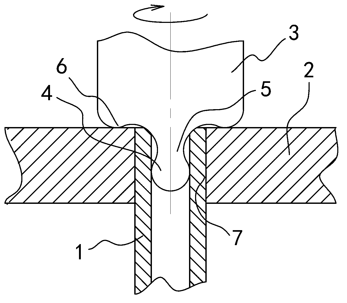
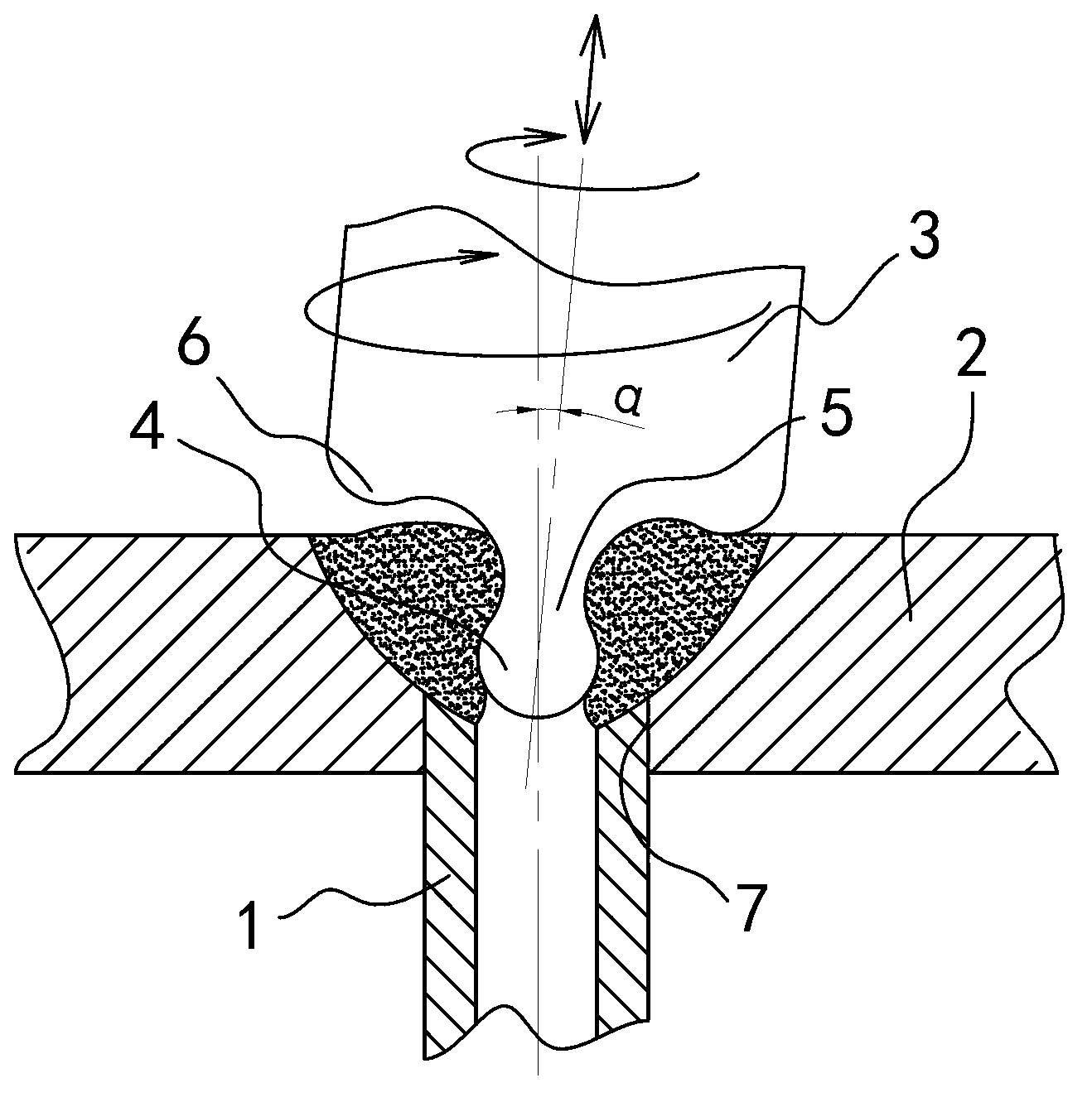
[0031] A new tube-sheet welding method, aiming at the connection objects of the tube 1 and the plate 2, adopts the rotating welding tool 3 to realize the welding of the tube 1 and the plate 2 through friction, stirring and upsetting.

[0032] (1) Welding tools

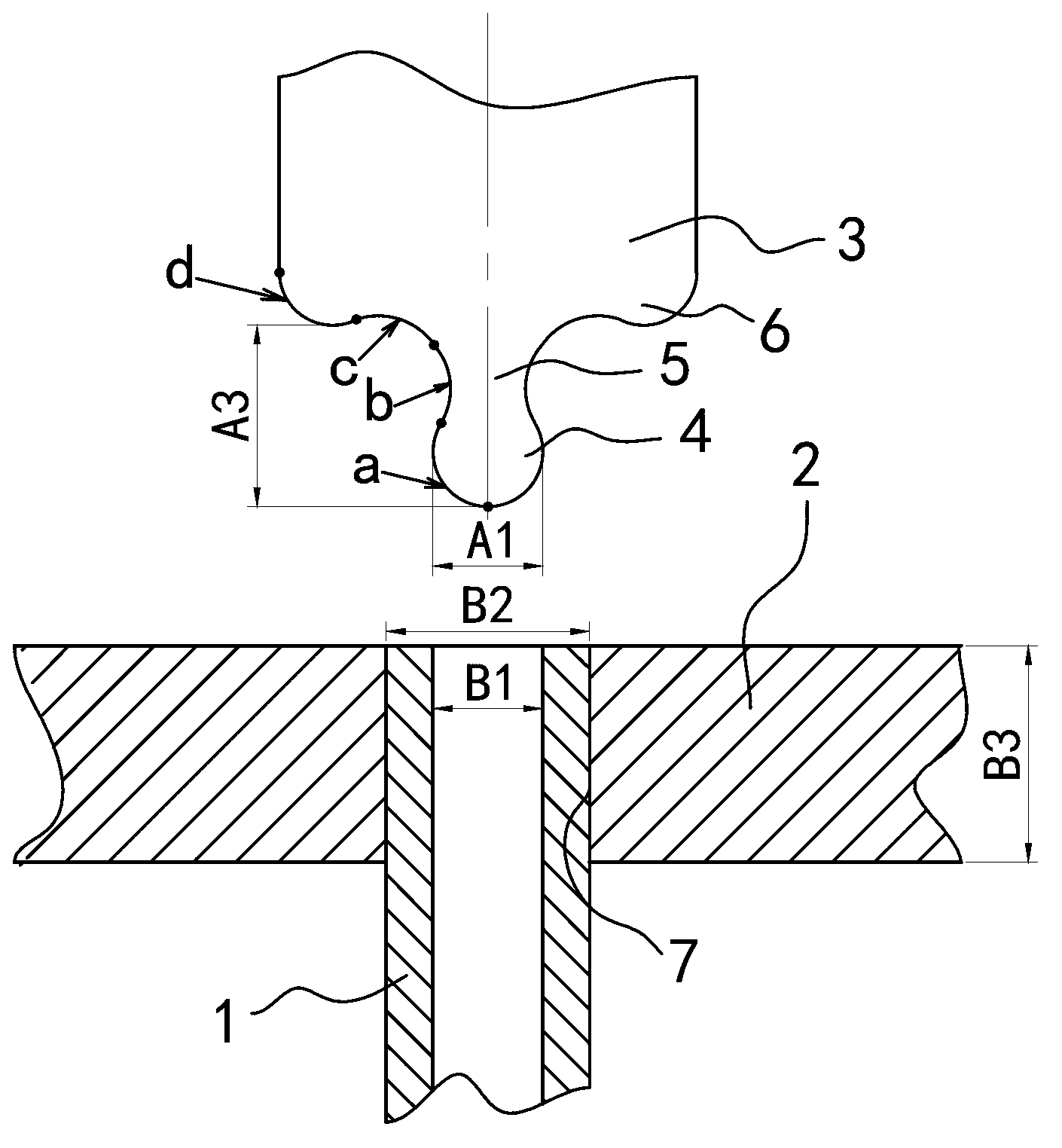
[0033] as attached figure 1 As shown, the welding tool 3 has a section of cylinder, and one end of the cylinder is the working end for welding, and the working end is a rotating body structure formed by rotating the generatrices of each section around the axis of the cylinder. The cylinder is composed of ball head 4, neck 5 and shoulder 6 in sequence in the axial direction. The ball head 4 is located at the center of the front end of the working end, the shoulder 6 is located at the peripheral position of the rear end of the working end, and the neck 5 is located at the center of the ball head. 4 and the position between the shoulder 6. The...

Embodiment 2

[0047] Embodiment two: see attached figure 1 - attached Figure 5 Shown:

[0048] A new tube-sheet welding method, aiming at the connection objects of the tube 1 and the plate 2, adopts the rotating welding tool 3 to realize the welding of the tube 1 and the plate 2 through friction, stirring and upsetting. The structure of the welding tool 3 and the welding steps are generally the same as the first embodiment, the difference is: the specific parameters of the tube 1 and the plate 2: the material of the tube 1 is aluminum alloy of 6063 grade, the outer diameter B2 of the tube 1 is 8mm, and the tube 1 The wall thickness is 1 mm, the material of the plate 2 is steel, the thickness B3 of the plate 2 is 5 mm, and the depth of the weld 8 required for welding is 3 mm. For this pipe 1 and plate 2, the apex diameter A2 of the fourth arc segment d on the shoulder 6 of the welding tool 3 can be set to about 12 mm, and the diameter A2 of the vertex of the ball head 4 of the welding too...


PUM


Abstract

Provided is a new tube plate welding method. The new tube plate welding method is characterized in that aiming at connecting objects which includes a tube and a plate, welding between the tube and the plate is achieved through adoption of a rotary welding set and modes of friction, stir and upsetting. According to the welding set, a working end of the welding set is composed of a ball head, a neck portion and shoulder portions in a connection mode in sequence, the diameter of the ball head is in interference fit with the inner diameter of the tube, the diameter of a peak of a fourth arc section on each shoulder portion is larger than the outer diameter of the tube, and a projection distance between the peak of the ball head and the peak of the fourth arc section on each shoulder portion in the axis direction is less than the thickness of the plate. The new tube plate welding method comprises the welding steps that (1) the tube is fixed with the plate in a support mode; (2) the ball head is inlaid into the tube; (3) the welding set rotates, and carries out circular pendulum motion and axial reciprocating motion at the same time, and therefore plastic deformation of materials of a combination portion between the plate and the tube is carried out; and (4) the welding set exits from the tube and the plate. The new tube plate welding method is applicable to welding between a thin wall tube and a thick plate, and has the advantages of being free from solder and scaling powder, high in welding intensity, environment-friendly, small in residual stress and deformation of a structure after welding, and the like.

Description

technical field [0001] The invention relates to a welding method, in particular to a tube plate welding method. The tube-sheet welding method is a solid-phase welding method similar to friction stir welding, which is specially used for butt pipes and plates. Background technique [0002] In the prior art, argon arc welding is usually used for welding tubes and plates. Argon arc welding requires solder, which is made of different materials from the masterbatch and has low strength. Moreover, due to the large heat-affected area during welding, the structure after welding The residual stress is large and easy to deform. [0003] In addition, there is a welding method called friction stir welding in the prior art. Friction stir welding is to extend the protruding section of a welding tool into the joint of the workpiece. Through the high-speed rotation of the welding tool, the protruding section of the welding tool rubs and stirs inside the material, and the shoulder of the we...

Claims


Application Information

Patent Timeline
Patent Type & Authority Applications(China)
IPC IPC(8): B23K20/12
Inventor 顾仁伏
Owner 苏州森光换热器有限公司
Why Eureka
Try Eureka