

Welding strip used in low-temperature welding mode and used for solar photovoltaic module
A solar photovoltaic and low-temperature welding technology, applied in the field of low-temperature welding ribbons, can solve problems such as huge costs, and achieve the effects of reducing breakage, reducing warpage, and ensuring welding reliability.
- Summary
- Abstract
- Description
- Claims
- Application Information
AI Technical Summary
Problems solved by technology
Method used
Image

Examples
Embodiment 1
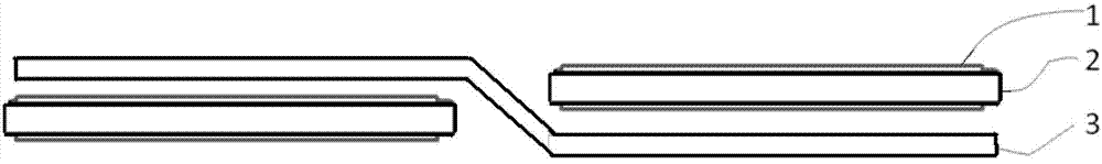
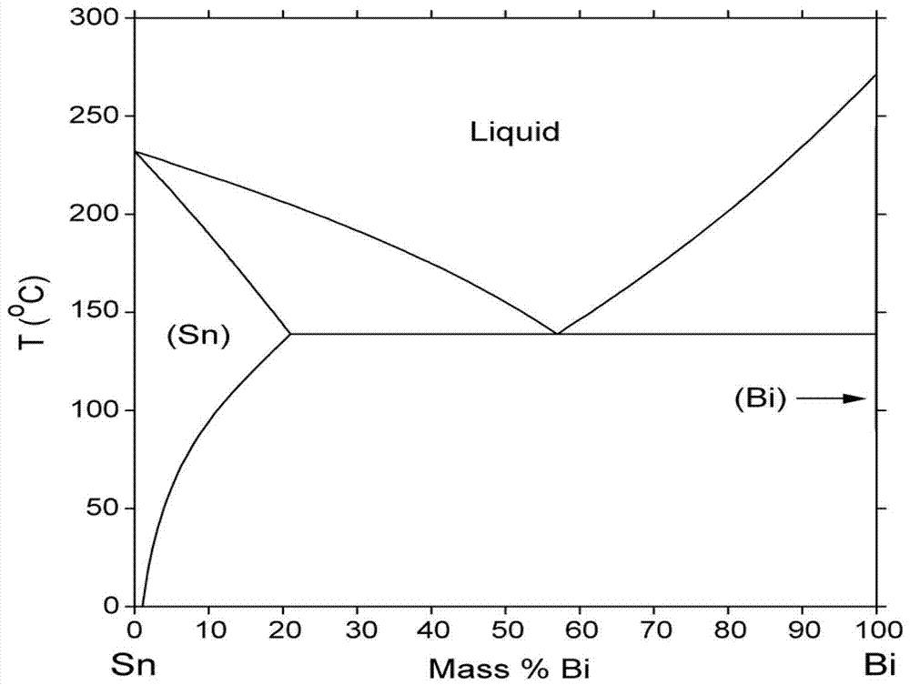
[0053] The commercially available solar tinned solder strip is hot-dipped with an alloy Bi58-Sn42 (ie Bi58wt%, Sn42wt%), and the thickness of the alloy coating is 20um. In order to detect the feasibility and applicability of the present invention, the solar cell sheet was prepared by the welding ribbon at a welding temperature of 200°C (the welding temperature of the common welding ribbon is 350°C), as image 3 shown. The solar cell adopts the commonly used backplane-EVA-cell-EVA-glass structure. A total of 6 solder ribbons are used for solar cells, 3 on the front and 3 on the back. In order to facilitate the subsequent test of contact resistance, the welding rods are numbered from left to right as 1, 2, and 3. The test data is shown in Table 1, which is close to that of ordinary welding strips. It can be seen that the welding strips have excellent performance.
[0054] Table 1
[0055]
Embodiment 2
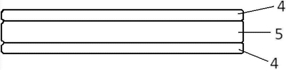
[0057]On a pure copper foil with a thickness of 0.1mm, Bi58-Sn42 (its melting point is 138.5°C) is electroplated, and the thickness of the alloy coating is 20um. All the other are with embodiment 1.
Embodiment 3
[0059] On a galvanized copper foil with a thickness of 0.1mm, hot-dip plating of Bi60-Cd40 (its melting point is 144°C). All the other are with embodiment 1.
PUM
| Property | Measurement | Unit |
|---|---|---|
| Melting point | aaaaa | aaaaa |
| Thickness | aaaaa | aaaaa |
| Thickness | aaaaa | aaaaa |
Abstract
Description
Claims
Application Information