Perforation big head slip casting constant resistant anchor rod

A technology of bolting and grouting, which is applied in the installation of bolts, mining equipment, earthwork drilling and mining, etc. It can solve the problems of failure of anchoring rock mass failure, reducing the strength of combined arches, increasing the anchoring area, etc., to achieve gas isolation, Prevents weathering and improves overall strength

Active Publication Date: 2013-06-26
尤洛卡(山东)矿业科技有限公司
View PDF6 Cites 7 Cited by
  • Summary
  • Abstract
  • Description
  • Claims
  • Application Information

AI Technical Summary

Problems solved by technology

The force of the anchor bolt supported by the existing anchor net is increased, and the failure of the anchored rock mass will occur, and the conical funnel structure under the stress of the anchor bolt will become smaller and reduce the strength of the composite arch.
The special application environment of large mining depth and high stress bolt-net support, soft rock bolt-net support and broken coal rock mass bolt-net support is difficult to adapt to the existing bolt-net support. Anchor rod, which should have the characteristics of increasing anchoring force, increasing anchoring area, enhancing combined arch strength, high-pressure grouting and constant resistance deformation; at the same time, it can release pressure with constant resistance deformation when subjected to rock impact, which is a guarantee for mine safety. production guarantee

Method used


Image

  • Perforation big head slip casting constant resistant anchor rod
  • Perforation big head slip casting constant resistant anchor rod
  • Perforation big head slip casting constant resistant anchor rod

Examples


Embodiment approach 1

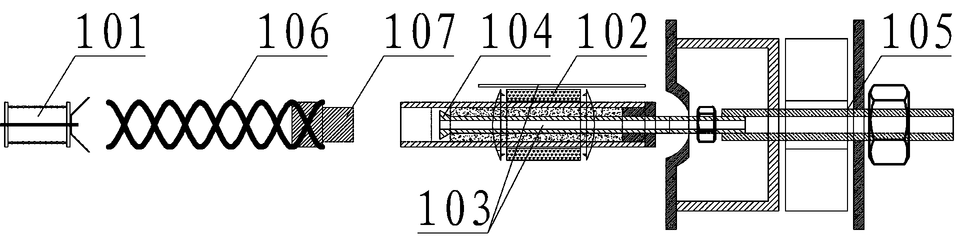
[0054] The perforated large-head grouting constant resistance anchor bolt forms a perforation crack at the end of the anchor bolt through the blasting perforation device 101, and then uses the O-shaped sealing drug roll device 102 to perform high-strength cracking at any reasonable position on the end, middle or tail of the anchor bolt. Anchor and seal, and then use the reserved high-pressure grouting device 103 to high-pressure grout in the broken coal rock mass (soft rock) at the end to form a large-headed anchor bolt, so that the original small contact area of ​​the conical funnel stress structure 601 becomes a large-end The stress-bearing structure 602 of the platform with a large area at the head increases the thickness of the combined arch to improve the overall strength of the support (such as Figure 6 shown). The blasting and perforating device 101, the O-shaped sealing drug coil device 102 and the high-pressure grouting device 103 can be used in conjunction with ordina...

Embodiment approach 2

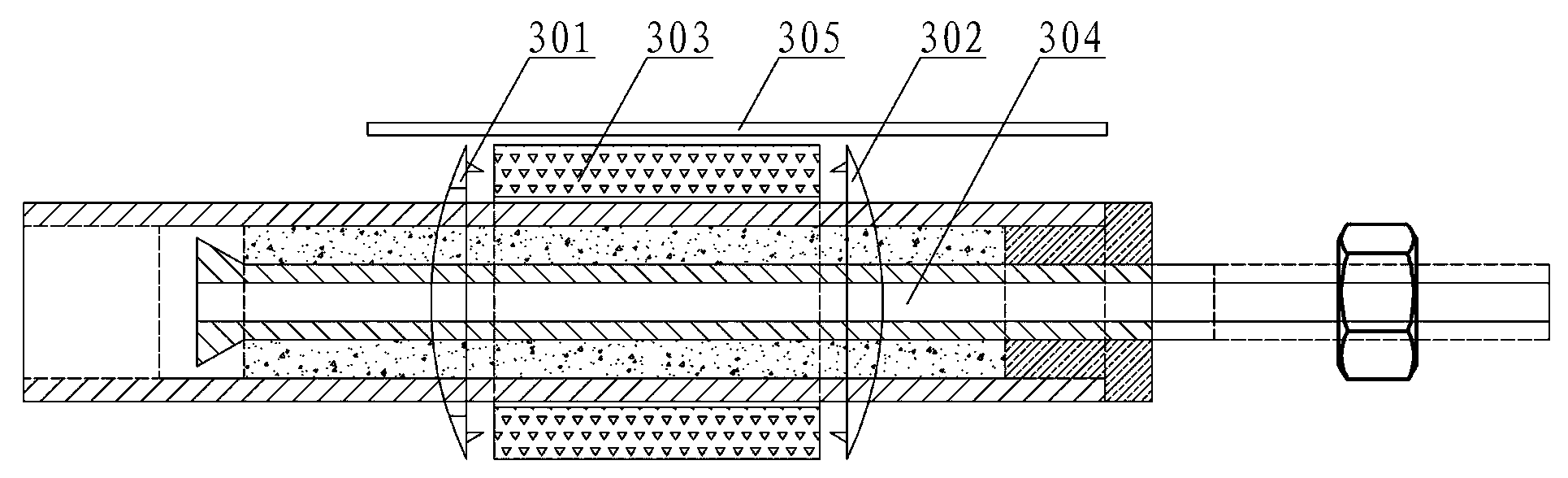
[0056] The lengthening detection device 105 of the perforating large head grouting constant resistance anchor rod is connected to the thread at the end of the anchor (cable) rod or the threaded anchor cable pressure flap through the lengthening connecting rod 502. 505 is set on the upper cover of the extended connecting rod, and the baffle plate 503 is tightened to detect the force situation. After the nut 504 on the extended connecting rod 502 is removed during the recovery process, the original anchor nut locks the anchor rod (the original anchor cable pressure flap lock Tighten the anchor cable), to prevent the failure of the anchor rod during the recovery process of the detection instrument 505, the excessive force on the anchor rod, the nut popping up and hurting people, and the detection instrument 505 being damaged and unable to be replaced. At the same time, the extended detection device 105 can be used with ordinary anchor (cable) rod The use achieves the effects of sa...

Embodiment approach 3

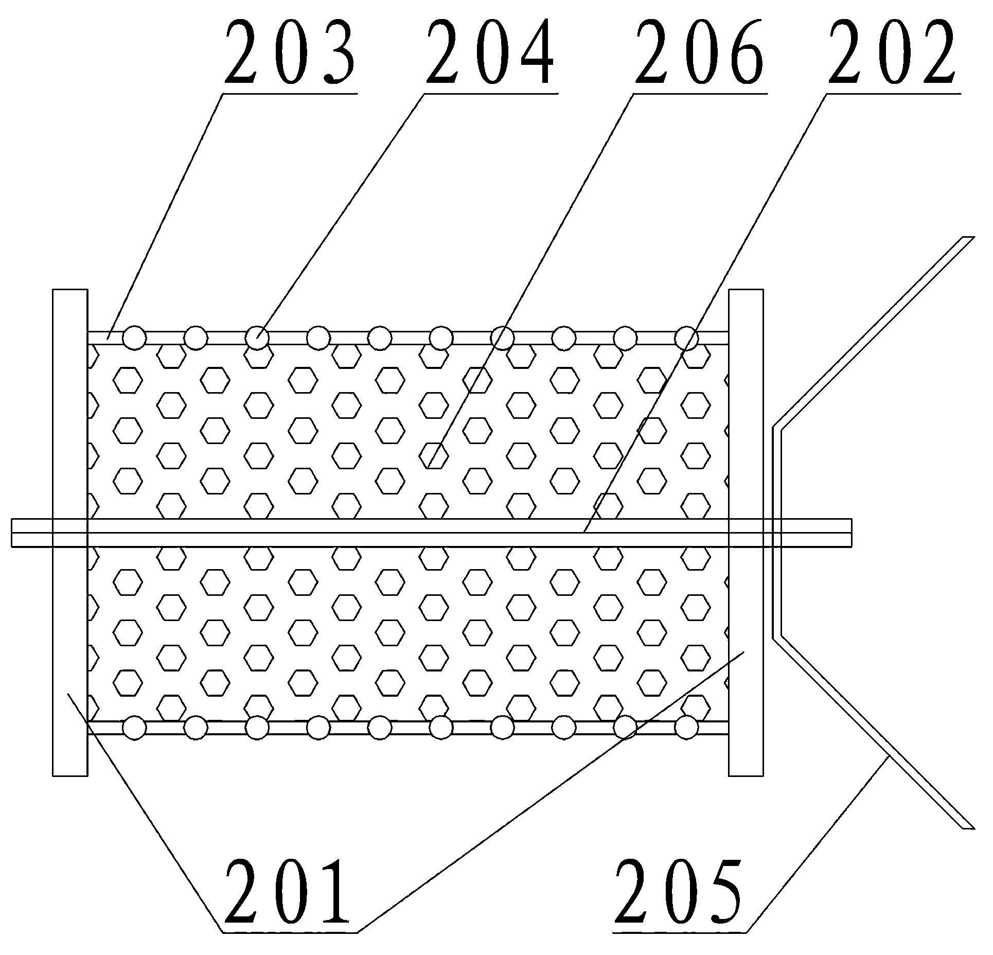
[0058] The constant resistance deformation device 104 of the perforated large head grouting constant resistance bolt is anchored on the bedrock through the outer casing 401, and the tail of the wedge head rod 403 is supported by a metal mesh, a tray and a nut to form an anchor mesh. When impacted, the O-shaped The resin deformation sleeve 402 deforms under force and constant resistance, which can effectively buffer the impact force and ensure the integrity of the support after buffer deformation and the constant resistance of the support strength. At the same time, the end of the perforated large-head grouting constant-resistance anchor rod is a threaded anchor cable connection structure 107 to form an extension anchor cable device 106. An extension anchor cable can be installed to form a constant resistance deformation anchor cable to improve the anchorage range of the anchor rod and the overall strength of the support. .


PUM


Abstract

The invention discloses a perforation big head slip casting constant resistant anchor rod in mining tunnel supporting equipment. The perforation big head slip casting constant resistant anchor rod mainly comprises an exploding perforation device, an O-shaped hole sealing power winding device, a high pressure slip casting device, a constant resistance deformation device, a lengthening detection device and an extending anchor rope device. The above-mentioned parts are used for forming a perforation big head slip casting constant resistant anchor rod structure. The exploding perforation device is used for enabling the perforation to be cracked at the end socket of the anchor rod. The O-shaped hole sealing power winding device is used for sealing the perforation and fixing the anchor rod in the middle or any other reasonable positions of the anchor rod. The high pressure slip casting device is used for injecting slurry to form the big head slip casting anchor rod in the end socket of the anchor rod. The constant resistance deformation device is arranged in the middle of the anchor rod. The lengthening detection device is arranged at the tail of the anchor rod. The extending anchor rope device is arranged at the end socket of the anchor rod. The problems that a cone stress structure of the end socket of the anchor rod cannot deform and detecting devices cannot be recycled are solved. The perforation big head slip casting constant resistant anchor rod has the advantages of constant resistance deformability, recycling of the detecting devices and a half-space stress structure of the big head of the end socket of the anchor rod, and build-up arch intensity of anchor rod supporting is strengthened.

Description

technical field [0001] The invention relates to a perforating big head grouting constant resistance bolt in support equipment. Background technique [0002] The anchor-mesh support method is widely used in mines, and the anchor-mesh-cable joint support method gradually replaces the existing shed support method, and the loose circle theory and the anchor-mesh composite arch stress structure have been mature; however, with the increase of mining depth and In soft rock problems, after the end of the bolt is anchored, the anchored rock mass is damaged in advance and the failure of the support often occurs. When the force of the anchor rod supported by the existing anchor net increases, the problem of failure of the anchored rock mass and the reduction of the strength of the combined arch due to the smaller conical funnel structure of the anchor rod will occur. The special application environment of large mining depth and high stress bolt-net support, soft rock bolt-net support ...

Claims


Application Information

Patent Timeline
Patent Type & Authority Applications(China)
IPC IPC(8): E21D21/00
Inventor 韩雪峰孙志涛袁小春
Owner 尤洛卡(山东)矿业科技有限公司
Why Eureka
Try Eureka