Light-emitting diode (LED) lighting device and manufacturing method of lamp support therein

A technology of LED lighting and lamp stand, which is applied in the cooling/heating device of the lighting device, the parts of the lighting device, the lighting device, etc., and can solve the problem of low dimensional accuracy and surface finish of the light stand, additional radiators, and poor heat dissipation effect Excellent heat dissipation effect, large heat conduction contact area, light weight effect

Inactive Publication Date: 2013-06-26
HANGZHOU HPWINNER OPTO CORP
View PDF7 Cites 2 Cited by
  • Summary
  • Abstract
  • Description
  • Claims
  • Application Information

AI Technical Summary

Problems solved by technology

[0008] The purpose of the present invention is to provide an LED lighting device to solve the technical problems that the existing LED lighting device needs to be additionally equipped with a radiator, the heat dissipation effect is not good, and the cost is high
[0009] The second object of the present invention is to provide a method for manufacturing a lamp holder in an LED lighting device, so as to solve the technical problems of low dimensional accuracy and surface finish of the lamp holder of the existing LED lighting device

Method used


Image

  • Light-emitting diode (LED) lighting device and manufacturing method of lamp support therein
  • Light-emitting diode (LED) lighting device and manufacturing method of lamp support therein
  • Light-emitting diode (LED) lighting device and manufacturing method of lamp support therein

Examples


Embodiment 1

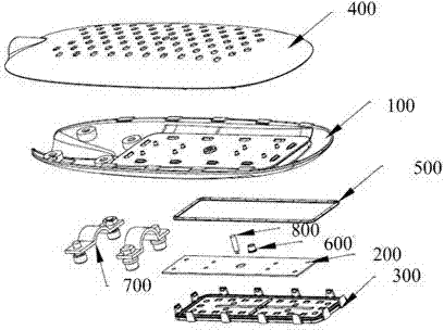
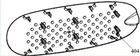
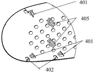
[0050] see Figure 1 to Figure 4 ,in, figure 1 An exploded view of the LED lighting device used as a street lamp provided by the first embodiment of the present invention, Figure 2A to Figure 2B It is a schematic structural diagram of the lamp cover in the LED lighting device used as a street lamp provided by the first embodiment of the present invention, image 3 It is a schematic structural diagram of the lamp holder in the LED lighting device used as a street lamp provided by the first embodiment of the present invention, Figure 4 The cross-sectional view of the LED lighting device used as a street lamp provided by the first embodiment of the present invention, such as Figure 1 to Figure 4As shown, the LED lighting device provided by the first embodiment of the present invention is used as a street lamp. The lighting device includes: a lamp holder 100, a circuit board (PCB board) 200, LED particles, a lens group 300, and a lamp cover 400. The lamp The cover 400 is fix...

Embodiment 2

[0060] The LED lighting device in this embodiment is used as a tunnel light. For the structure of the LED lighting device provided in this embodiment, please refer to Figure 5 , Figure 5 A schematic structural diagram of an LED lighting device used as a tunnel light provided in the second embodiment of the present invention, as shown in Figure 5 As shown, the LED lighting device in this embodiment differs from the LED lighting device provided in the first embodiment in that:

[0061] 1) The LED lighting device of this embodiment does not include a lamp cover;

[0062] 2) The LED lamp stand 900 of this embodiment is provided with a support rod and a mounting bracket 204, specifically, the support rod includes two vertical rods and a horizontal rod, the two vertical rods are connected with the lamp stand 900, and the horizontal rod It is fixed on the two vertical bars, the LED driving power supply 203 is placed on the horizontal bar, and the mounting bracket 204 is connecte...

Embodiment 3

[0065] The LED lighting device in this embodiment is used as a mine lamp. For the structure of the LED lighting device provided in this embodiment, please refer to Figure 6 , Figure 6 A schematic structural diagram of an LED lighting device used as a factory lamp provided by the third embodiment of the present invention, as shown in Figure 6 As shown, the LED lighting device in this embodiment differs from the LED lighting device provided in the first embodiment in that:

[0066] 1) The LED lighting device of this embodiment does not include a lamp cover;

[0067] 2) The LED lamp stand 900 of this embodiment is provided with a support rod and a mounting bracket 204, specifically, the support rod includes two vertical rods and a horizontal rod, the two vertical rods are connected with the lamp stand 900, and the horizontal rod It is fixed on the two vertical bars, and the LED driving power supply 303 is placed on the horizontal bar. The mounting bracket 304 also includes t...


PUM


Abstract

The invention discloses a light-emitting diode (LED) lighting device which comprises a lamp support, a circuit board, LED particles and a lens group. The LED particles are arranged on the circuit board, and the lens group is buckled on the lamp support upside down. The lamp support is made of metal plates through a drawing technology and is provided with a groove, the groove and the circuit board form a closely fitting structure, a radiator is disposed between the groove and the circuit board, and the LED light device dissipates heat through the lamp support. The LED lighting device does not need additional radiators, the aluminum lamp support made through the drawing technology has the same or even more excellent radiating effect than the aluminum lamp support made through a casting technology only one third to one fifth material is need using, and thus cost is reduced greatly, and the heat conductivity coefficient of drawing aluminum is high, and radiating effect is good.

Description

technical field [0001] The invention relates to the lighting field, in particular to an LED lighting device and a method for manufacturing a lamp holder in the LED lighting device. Background technique [0002] Light Emitting Diode (LED, Light Emitting Diode) is a semiconductor that can convert electrical energy into light energy. It changes the principle of incandescent lamp tungsten filament luminescence and energy-saving lamp trichrome luminescence, and uses electric field luminescence. [0003] LED lamps have the advantages of energy saving, long life, good applicability, short response time, environmental protection, gorgeous colors, and pure luminous colors. They are the development direction of the lamp industry. [0004] For existing high-power lamps such as LED street lamps, tunnel lamps, and industrial and mining lamps, the LED light source is often welded to a whole aluminum substrate, then fixed on the radiator, and then sealed into the lamp housing, thereby affe...

Claims


Application Information

Patent Timeline
Patent Type & Authority Applications(China)
IPC IPC(8): F21S8/00F21V21/10F21V29/00F21V31/04F21Y101/02F21V29/83F21V29/89F21Y115/10
Inventor 陈凯黄建明
Owner HANGZHOU HPWINNER OPTO CORP
Why Eureka
Try Eureka