
Flow guide structure inside hot end of U-type / linear pulse tube refrigerating machine and manufacturing method thereof

A technology of pulse tube refrigerator and pulse tube refrigerator, which is applied in refrigerators, gas cycle refrigerators, refrigeration and liquefaction, etc., can solve the problems of cooling efficiency reduction, affecting heat exchange efficiency, affecting gas flow speed, etc. The effect of improving the conduction performance, increasing the heat exchange area, and improving the cooling efficiency

Inactive Publication Date: 2013-06-26
SHANGHAI INST OF TECHNICAL PHYSICS - CHINESE ACAD OF SCI
View PDF6 Cites 6 Cited by
  • Summary
  • Abstract
  • Description
  • Claims
  • Application Information

AI Technical Summary

Problems solved by technology

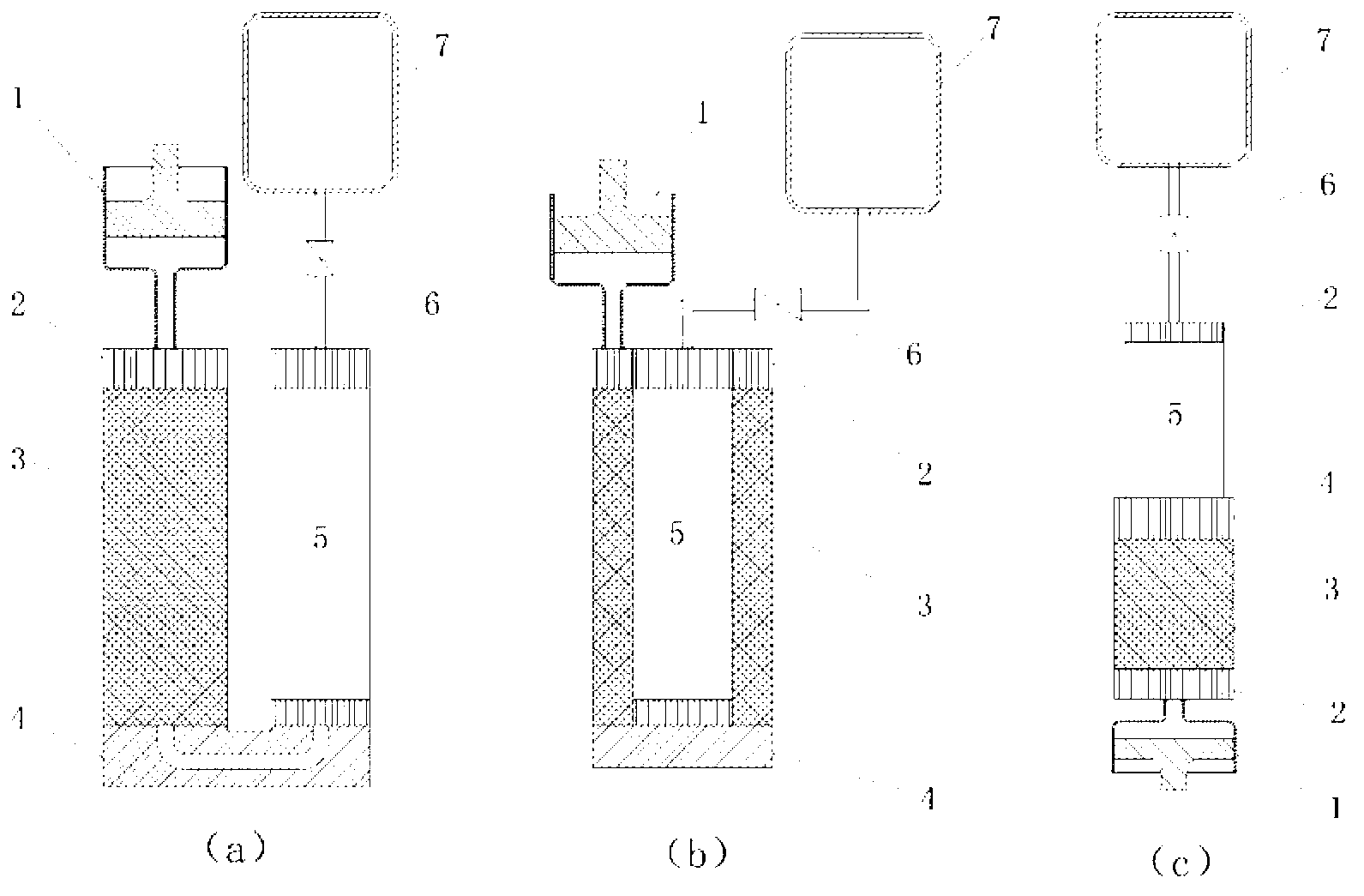
Three layout forms, the linear internal flow resistance is small, in actual use, the overall body is large and it is not easy to couple with the cooled device; the U-shaped pulse tube and the regenerator are arranged side by side, the overall structure size is reduced, but the 180-degree turning Increase the flow resistance; the coaxial structure is more compact, and the cold end protrudes separately, but the flow resistance is greater
[0014] The first form, such as Figure 4 , the central through hole 12 of the hot end plug 8 with a small aperture should be connected with the slit body 10 with a large cross-section, and the opening at the upper end of the hot end plug 10 is made into a cylindrical groove 13, and the gas passes through the center of the hot end plug 8 After the hole 12 flows out, it diffuses and enters the slit body 10. Because the opening is made into a cylinder, although the corners of the bottom are rounded and transitioned, the gas flowing out of the through hole 12 in the center of the hot end plug 8 will only form On the fan-shaped diffuser surface, there will be an airflow low-pressure area 14 at the bottom corners of the four sides, resulting in the generation of eddy currents, which seriously affects the flow velocity of the gas, which will greatly reduce the efficiency of the refrigerator
[0015] The second form, such as Figure 5 , the opening form of the junction of the hot end plug 8 and the slit body 10 is made into a conical shape, which eliminates the low pressure area of ​​the airflow around the bottom corner of the cylindrical groove, but because the gas in the pulse tube refrigerator is always in a state of high frequency oscillation , the gas passes through the conical opening 13 in an alternating flow state, so when the gas flows into the conical opening 13 from the central through hole 12 of the hot end plug 8, a situation occurs, and the fast-moving gas does not move along in a straight line. The straight conical surface enters the edge area of ​​the slit body 10, and the space at the corners of the conical opening 13 is narrow, so that the gas here cannot pass through the slit body 10 as quickly as the gas in the central area of ​​the conical opening 13, resulting in The gas flow rate is slow to form a gas stagnation area, that is, the gas flow dead angle 14. Such a situation makes the gas fail to enter along the entire coverage of the slit body 10, but a protruding state appears in the middle, so that the gas flowing into the slit body 10 Laminarization cannot be fully realized, and the heat exchange efficiency between the gas and the fins in the slit body 10 is affected, resulting in a reduction in refrigeration efficiency

Method used


Image

  • Flow guide structure inside hot end of U-type / linear pulse tube refrigerating machine and manufacturing method thereof
  • Flow guide structure inside hot end of U-type / linear pulse tube refrigerating machine and manufacturing method thereof
  • Flow guide structure inside hot end of U-type / linear pulse tube refrigerating machine and manufacturing method thereof

Examples


Embodiment Construction

[0037] Below in conjunction with accompanying drawing and example the specific embodiment of the present invention is described in further detail;

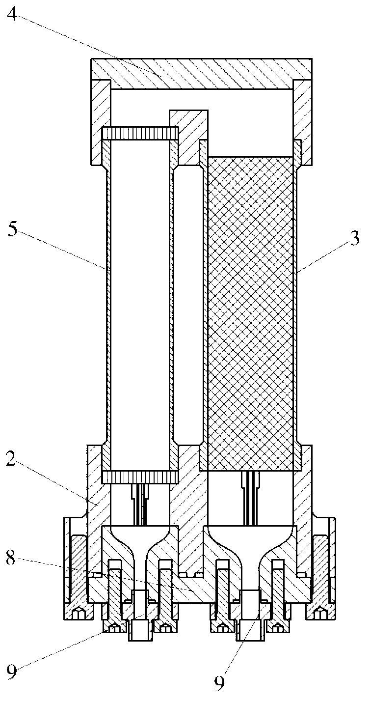
[0038] Figure 6 It is a detailed schematic diagram of the internal flow guide structure at the hot end of the invented U-shaped and linear pulse tube refrigerator, including the hot end heat exchanger 2, the cold storage device 3, the flow guide stem 11, the hot end plug 8, and the flow of the internal gas distributed.

[0039] Figure 7 A cross-sectional schematic diagram of the plug at the hot end.

[0040] The invented internal diversion structure at the hot end of the U-shaped and linear pulse tube refrigerator is composed of three parts: the hot end heat exchanger 2, the diversion stem 11, and the hot end plug 8. It is characterized in that the hot end heat exchanger 2. The step hole 18 at the upper end is inserted into the regenerator 3 and the pulse tube 5, and welded together. The inner center of the hot end heat excha...


PUM


Abstract

The invention discloses a flow guide structure inside the hot end of a U-type / linear pulse tube refrigerating machine and a manufacturing method of the flow guide structure. The flow guide structure is composed of a hot end heat exchanger, a hot end plug and a flow guide core column. Cone-shaped fin structures are formed in the hot end heat exchanger in a cutting mode through the wire cutting technology and are evenly distributed around the center of the hot end heat exchanger in a ring-shaped mode. A T-shaped through hole is formed in advance in the central portion before a wire cutting process so as to eliminate a thin and weak sharp corner at the tail end of each fin. The flow guide core column which is also manufactured in a fin structure is inserted into the hot end heat exchanger, and a hole is formed in the central position of the flow guide core column in a penetrating mode. The hot end plug is inserted into the hot end heat exchanger, wherein a transition curved surface, which changes gradually in two directions inside the hot end plug is connected with slit body flow guide passageways and small hole channels, the curved surface is tangent to the surface of each of fluid passageways at two ends, and the hot end plug is tightly connected on the hot end heat exchanger through a sealing ring and screws. Through the design of the novel flow guide structure at the position of abrupt change of the cross section of a hot end gas flow passageway, loss of high-frequency oscillation gas flow at the position is enabled to be minimized, and the flow guide structure inside the hot end of the U-type / linear pulse tube refrigerating machine has important significance in improving refrigerating efficiency of the U-type / linear pulse tube refrigerating machine.

Description

technical field [0001] The invention relates to a pulse tube refrigerator, in particular to a hot end internal flow guide structure and a manufacturing method of a U-shaped and linear pulse tube refrigerator. Background technique [0002] The pulse tube refrigerator was born in the 1960s and has been put into large-scale practical application since the 1990s. Compared to the G-M refrigerator and the Stirling refrigerator, the pulse tube refrigerator eliminates the ejector in the low temperature region and replaces it with a hollow tube called a pulse tube. Its phase is controlled by static components such as small holes, inertial tubes and gas reservoirs installed at the hot end of the pulse tube. Since there are no moving parts in the low temperature area, problems such as sliding wear, mechanical vibration, gap sealing, etc. are eliminated. Therefore, the pulse tube refrigerator has the advantages of small vibration and long life, and the refrigeration efficiency in the ...

Claims


Application Information

Patent Timeline
Patent Type & Authority Applications(China)
IPC IPC(8): F25B9/14B23P15/26
CPCF25B2309/1406
Inventor 党海政周炳露宋宇尧
Owner SHANGHAI INST OF TECHNICAL PHYSICS - CHINESE ACAD OF SCI
Learn More