Digital display scope (DDS) signal generator and amplitude control method thereof

A signal generator and amplitude control technology, applied in the direction of digital function generators, etc., can solve the problems of 1uHz distance, data DAC vertical resolution gain DAC data bit width reduction, loss of precision, etc., to solve damage and avoid nonlinearity distortion effect

Active Publication Date: 2013-06-26
RIGOL
View PDF3 Cites 12 Cited by
  • Summary
  • Abstract
  • Description
  • Claims
  • Application Information

AI Technical Summary

Problems solved by technology

[0005] (1) Its output waveform can only be a sine wave and cannot be used as a function/arbitrary waveform generator;
[0006] (2) The phase accumulator is 32 bits, and the frequency resolution can only be 29mHz, which is far from the 1uHz of the mainstream signal generator;
[0007] (3) The phase control word is 8 bits, and the phase resolution is only 1.4o, while many signal generators have a phase accuracy of 0.01o or even 0.001o;
[0008] (4) The sampling rate is only 125MHz, which cannot meet the current market demand for signal generators with high sampling rate and high bandwidth
[0010] (1) The multiplier and amplitude DAC will increase the area of ​​the printed circuit board, cor

Method used


Image

  • Digital display scope (DDS) signal generator and amplitude control method thereof
  • Digital display scope (DDS) signal generator and amplitude control method thereof
  • Digital display scope (DDS) signal generator and amplitude control method thereof

Examples


Embodiment 1

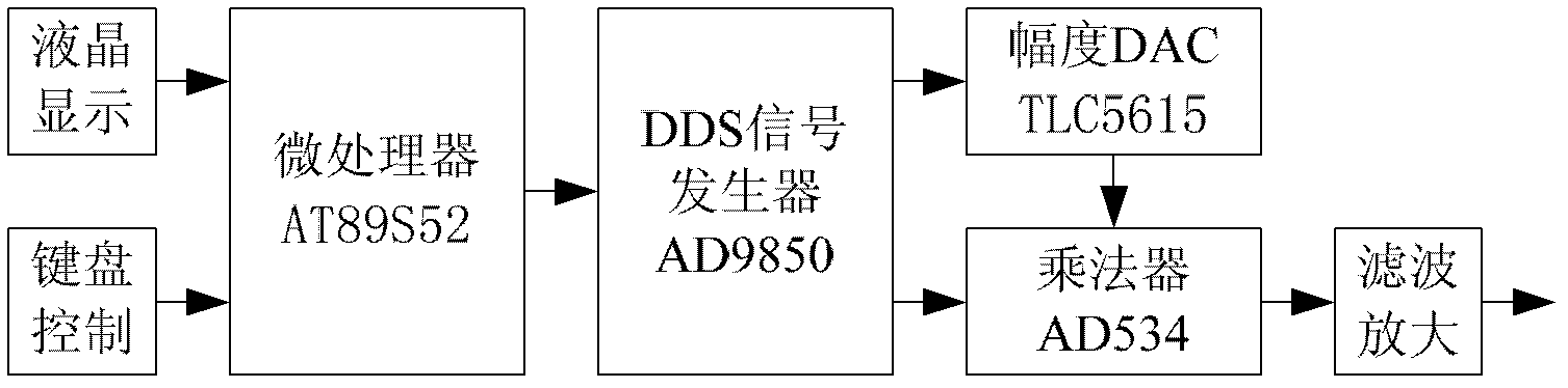
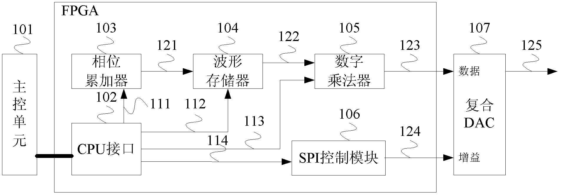
[0036] There are many deficiencies in implementing a signal generator with a dedicated DDS chip, mainly because of poor flexibility. Therefore, the signal generator in the embodiment of the present invention uses a programmable logic array (FPGA) to implement DDS, and its basic structure is FPGA+DAC. The FPGA generates digital waveforms, and the digital-to-analog converter (DAC) converts them into analog quantities. Phase accumulator, waveform memory, and digital-to-analog converter are the basic structures of DDS technology to generate signals.

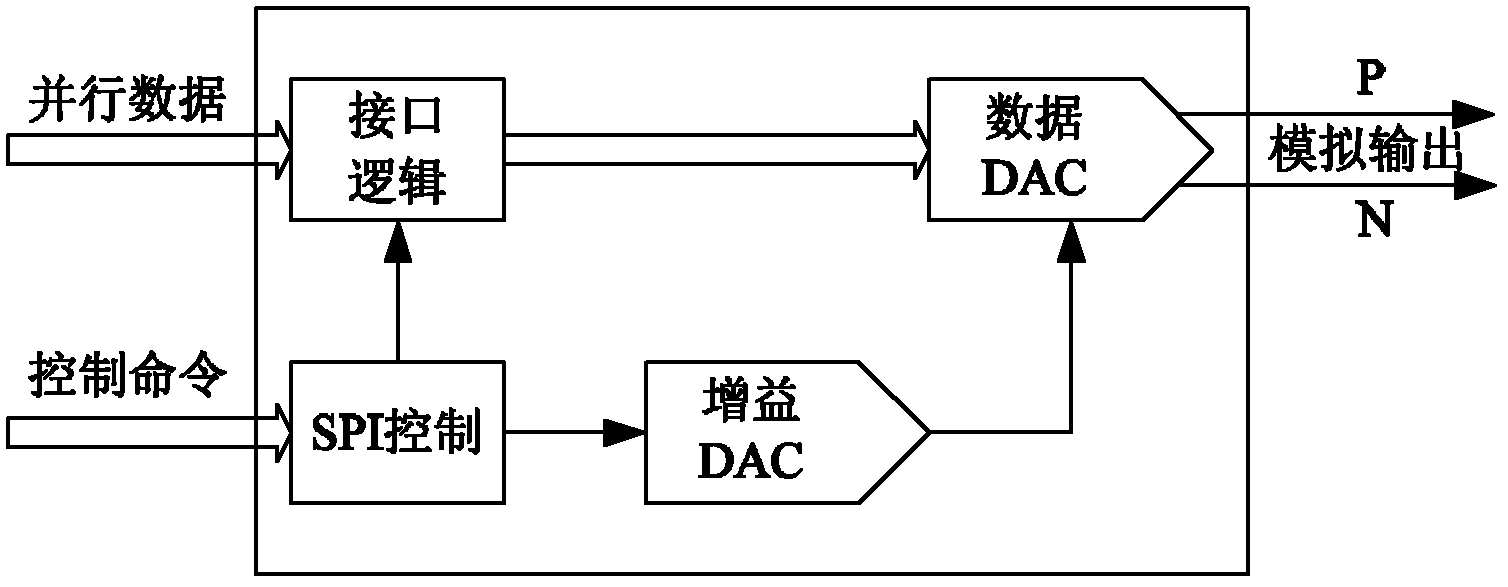
[0037]Aiming at the structure of FPGA+DAC, the embodiment of the present invention proposes a DDS signal generator and its amplitude control method, and the FPGA and the gain DAC cooperate to complete the signal amplitude compensation. Specifically, in this embodiment, a digital multiplier is added inside the FPGA, and together with the gain DAC integrated inside the composite DAC, fine control of the DDS signal amplitude is realize...

Embodiment 2

[0059] In Embodiment 1, the maximum amplitude of the waveform samples in the waveform memory 104 is constant. This embodiment provides another DDS signal generator and its amplitude control method. This solution does not use a digital multiplier, but the control unit 101 directly adjusts the amplitude of the waveform samples written into the waveform memory according to the requirements of amplitude control, so as to realize amplitude control and solve the loss of vertical resolution. The FPGA+DAC internal block diagram of this embodiment is as Figure 5 As shown, the functions of each module are as follows:

[0060] (1) The main control unit 101 controls the work of the entire signal generator, which can be performed by a DSP processor or other general-purpose processors; specifically, the main control unit 101 configures the amplitude compensation coefficient and the reference voltage value, so that the amplitude compensation coefficient The sum of the bit width of the ref...


PUM


Abstract

The invention discloses a digital display scope (DDS) signal generator and an amplitude control method of the digital display scope (DDS) signal generator. The DDS signal generator comprises a main control unit, a field programmable gata array (FPGA) module connected with the main control unit and a composite DAC connected with the FPGA module, wherein the main control unit is used for allocating amplitude compensation coefficients and reference voltage values so as to enable a sum of a bit wide of the amplitude compensation coefficients and the bit wide of the reference voltage values to be bigger than or equal to the bit wide of wave form sampling points. The FPGA module comprises a wave form storage used for storing wave form sampling points, a digital multiplier used for multiplying the wave form sampling points by the amplitude compensation coefficients to obtain a wave form digital quantity and sending the wave form digital quantity to a data DAC installed inside the composite DAC and a signal program initiation (SPI) control module is used for converting the reference voltage values into an SPI form and sending to a gain DAC installed inside the composite DAC, and the composite DAC converts wave form figures in the data DAC into an analogy quantity according to the reference voltage values in the gain DAC.

Description

technical field [0001] The present invention relates to the technical field of signal generators, in particular to the amplitude control technology of a Direct Digital Frequency Synthesis (DDS, Direct Digital Frequency Synthesis) signal generator, specifically a DDS signal generator and an amplitude control method thereof. Background technique [0002] In the actual communication process, the system has high requirements on frequency accuracy and stability, and often needs to use a variety of signals with different frequencies and phases. Traditional waveform generators are implemented by analog circuits, limited by hardware circuits, not only generate fewer waveforms, but also have low precision, but also have large volume and poor flexibility. DDS technology is a new frequency synthesis technology that directly synthesizes the required waveform from the concept of phase; DDS signal generator has the advantages of fast frequency conversion, high resolution, wide frequency s...

Claims


Application Information

Patent Timeline
IPC IPC(8): G06F1/03
Inventor 丁新宇王悦王铁军李维森
Owner RIGOL
Why Eureka
Try Eureka