
Method for eliminating circular symmetry phase computer-generated holography substrate fringe pattern distortion

A technology for calculating holography and graphic distortion, which is applied in the field of optical detection to improve detection accuracy, achieve high-precision detection, and achieve high-precision effects

Inactive Publication Date: 2015-05-20
INST OF OPTICS & ELECTRONICS - CHINESE ACAD OF SCI
View PDF4 Cites 0 Cited by
  • Summary
  • Abstract
  • Description
  • Claims
  • Application Information

AI Technical Summary

Problems solved by technology

This method is to use the ideal point light source emitted by two single-mode optical fibers to produce Young's interference fringes and the Moiré fringes formed by the mutual interference of the etched straight fringes on the hologram to obtain the fringe pattern distortion value on the hologram. This method can only detect Straight stripes, but the stripes etched on the hologram used at this stage are mostly circular symmetrical stripes

Method used


Image

  • Method for eliminating circular symmetry phase computer-generated holography substrate fringe pattern distortion
  • Method for eliminating circular symmetry phase computer-generated holography substrate fringe pattern distortion
  • Method for eliminating circular symmetry phase computer-generated holography substrate fringe pattern distortion

Examples


Embodiment Construction

[0025] The present invention will be further described in detail below in conjunction with the accompanying drawings and specific embodiments.

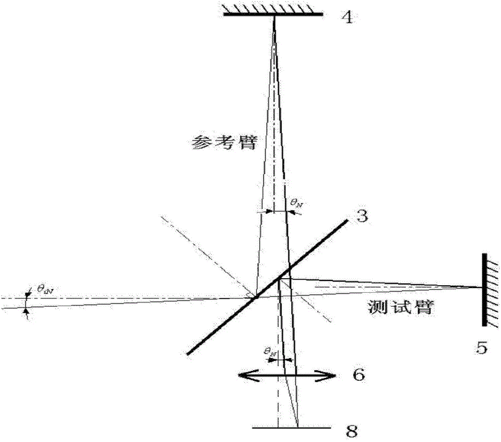
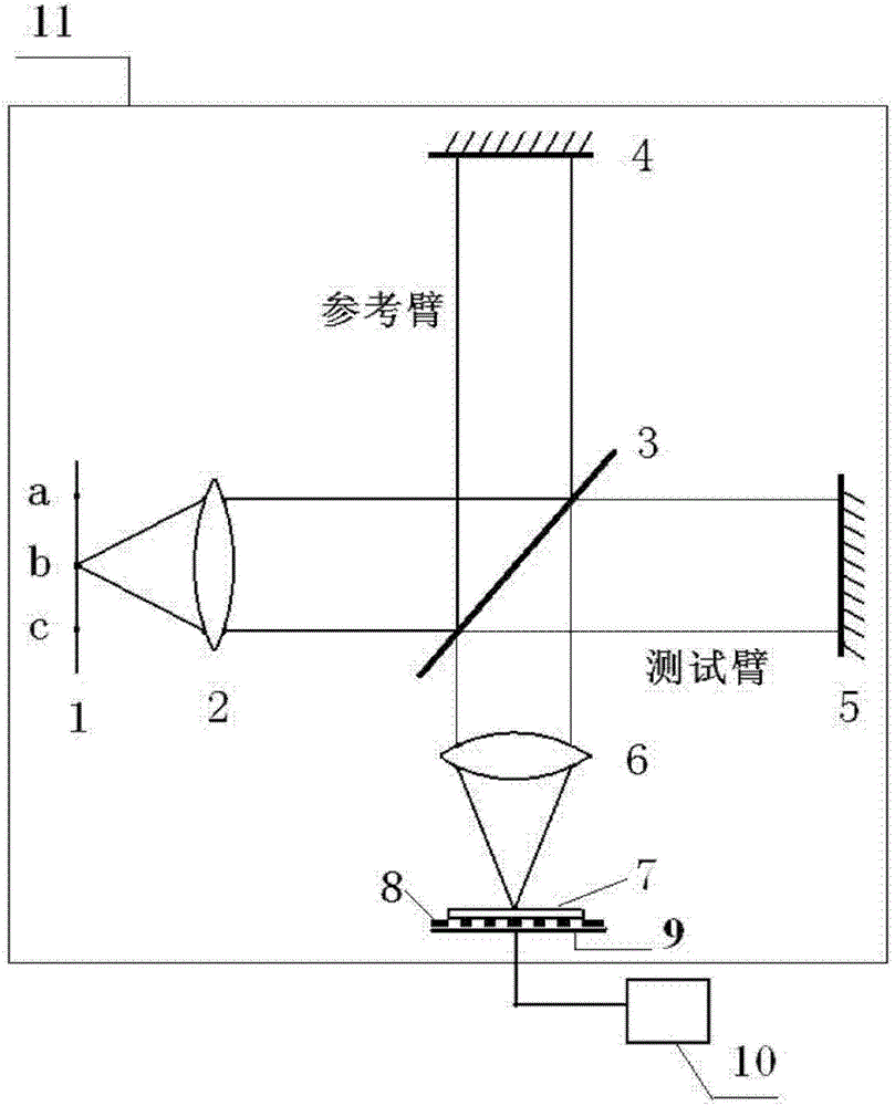
[0026] Such as figure 1 A schematic diagram of the Tyman-Green isoclinic interference is shown. The Tyman-Green interference contains a beam splitter 3, mirrors 4 and 5, and a converging lens 6. The light emitted from the extended light source 1 is any three light source points on the extended light source 1. The light emitted by the light source point b in a, b, and c is collimated by the collimator lens 2 and then reaches the beam splitter 3. The beam splitter 3 splits the light into two beams, one of which is reflected by the beam splitter 3 and reaches the reflector 4. The light reflected by it passes through the beam splitter 3, and after passing through the converging lens 6, the light is converged on the focal plane; the other beam of light passes through the beam splitter 3, is reflected back by the mirror 5, and then reaches ...


PUM


Abstract

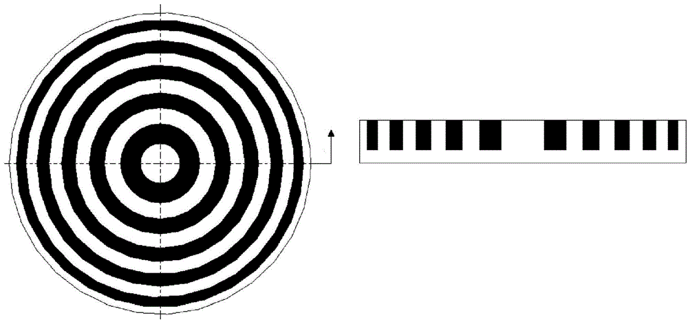
The invention provides a method for eliminating circular symmetry phase computer-generated holography substrate fringe pattern distortion. After light emitted from an expanding light source passes through two arms of a Twyman-Green interferometer, equal inclination interference occurs, equal inclination interference circular fringes which are sparse in the center and dense on edges are generated and recorded through an electric coupling device, a circular grating is generated through concentric circular fringes which are generated through the equal inclination interference, and a computer-generated holography substrate is processed through opaque liquid so that a circularly symmetric two-value amplitude type grating is generated; the concentric circular strips etched on the circularly symmetric two-value amplitude type grating and the equal inclination interference circular fringes on the circular grating are set so that a moire fringe condition is formed; and a moire fringe pattern with fringe pattern distortion information and a moire fringe pattern without the fringe pattern distortion information are recorded through a computer, the two moire fringe patterns are compared, data are processed so that a computer-generated holography substrate fringe pattern distortion value is obtained, influence on an aspheric surface detection result by the computer-generated holography substrate fringe pattern distortion is eliminated through an artificially synthesized distortion pattern, and aspheric surface high-accuracy detection is achieved.

Description

technical field [0001] The invention belongs to the field of optical detection, and relates to a method for eliminating the influence of the fringe pattern distortion of a circular symmetric phase type computational hologram substrate (Computer Generated Hologram) on the detection result of an aspheric surface. Background technique [0002] Aspheric elements are more and more widely used because they can reduce the complexity of the optical system and improve the imaging quality of the system, but the high-precision aspheric surface shape detection is still a hot and difficult point in current research. Computational hologram (Computer-generated hologram, CGH) is commonly used to detect aspheric surfaces. This technology can generate reference wavefronts of almost any shape from spherical waves through diffraction. This feature makes it possible to combine laser interferometers to zero Bit-compensated optical detection, which has the advantages of high efficiency and high pr...

Claims


Application Information

Patent Timeline
Patent Type & Authority Patents(China)
IPC IPC(8): G01B11/24
Inventor 冯婕邓超姚政鹏邢廷文
Owner INST OF OPTICS & ELECTRONICS - CHINESE ACAD OF SCI
Learn More