Pneumatic-control optical limiter

A technology of air pressure control and optical limiting, which is applied in the direction of instruments, optics, nonlinear optics, etc., can solve the problems that the optical limiter or material cannot be adjusted in real time, it is difficult to meet the use requirements, and the changeable application environment, etc., achieves Real-time light clipping, easy operation, and stable adjustment effect

Active Publication Date: 2013-07-10
SHANGHAI INST OF OPTICS & FINE MECHANICS CHINESE ACAD OF SCI
View PDF3 Cites 8 Cited by
  • Summary
  • Abstract
  • Description
  • Claims
  • Application Information

AI Technical Summary

Problems solved by technology

Although optical limiting materials based on new materials such as graphene have been deeply researched and developed rapidly, the current optical limiters or materials cannot be adjusted in real time, and it is difficult to meet the use requirements in changing application environments

Method used


Image

  • Pneumatic-control optical limiter

Examples


Embodiment 1

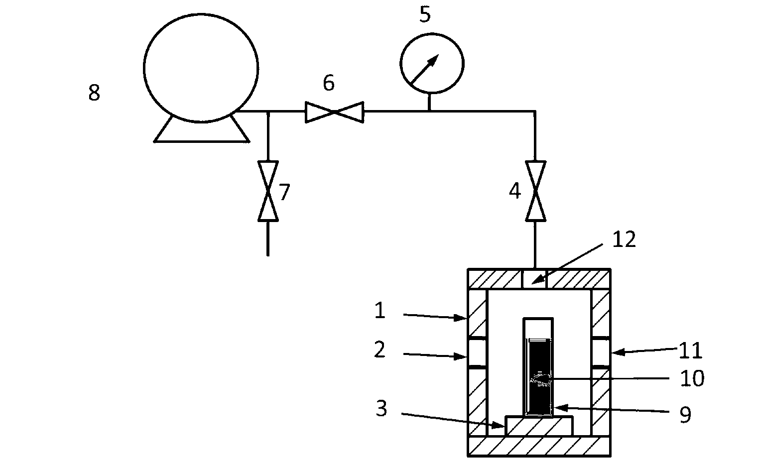
[0018] see first figure 1 , figure 1 It is the schematic diagram of the device of embodiment 1 of the optical limiter controlled by air pressure of the present invention. As can be seen from the figure, the optical limiter controlled by air pressure of the present invention comprises a cylindrical sealed cavity 1, and the opposite surface of the sealed cavity 1 is provided with a first The transparent window 2 and the second transparent window 11 are provided with a cylindrical sample stage 3 at the center of the bottom surface in the sealed chamber 1; a rectangular parallelepiped transparent container 9 is arranged at the center of the cylindrical sample stage 3, and the transparent container 9 The two opposite surfaces are parallel to the first transparent window 2 and the second transparent window 11; a nonlinear scattering medium 10 is installed in the transparent container, and the nonlinear scattering medium 10 is dispersed in an organic solvent or a surfactant solution,...


PUM


Abstract

A pneumatic-control optical limiter comprises a sealing cavity and a decompress system. Characteristics that nonlinear scattering effect of nonlinear scattering media is relative to solvent boiling point are adopted by the optical limiter; and by means of adjusting air pressure around the nonlinear scattering media, real-time control on response of optical limiting is realized. Real-time and quantitative adjustment on the response of optical limiting can be realized with the pneumatic-control optical limiter which can be applicable to laser protection and laser control of sensitive optical elements.

Description

technical field [0001] The invention relates to an optical limiter, in particular to an optical limiter controlled by air pressure. Background technique [0002] The development of modern laser technology has made laser widely used in the fields of distance measurement, radar and communication, but what follows is that the strong laser can easily cause damage to the human eye and the photoelectric equipment in the system, so the safety protection of dangerous laser become an urgent need. [0003] An optical limiter refers to a material or device that has the following properties: when irradiated by a laser, it has high transmittance under low-intensity laser irradiation and low transmittance under high-intensity laser irradiation. The optical clipping process is realized by using nonlinear materials such as single-walled carbon nanotubes, multi-walled carbon nanotubes, and graphene through nonlinear optical effects such as nonlinear absorption, nonlinear refraction, or nonl...

Claims


Application Information

Patent Timeline
Patent Type & Authority Applications(China)
IPC IPC(8): G02F1/35
Inventor 程鑫王俊王康鹏董宁宁张晓艳张龙
Owner SHANGHAI INST OF OPTICS & FINE MECHANICS CHINESE ACAD OF SCI
Why Eureka
Try Eureka