Built-in permanent magnet memory motor of magnetic flux switching type

A memory motor, magnetic flux switching technology, applied in the magnetic circuit shape/style/structure, synchronous machine parts, magnetic circuit static parts and other directions, can solve the difficulty of the excitation current control system and increase the complexity of electromagnetic characteristics , the magnetic flux is easy to couple with each other, etc., to achieve the effect of easy heat dissipation, improve operating efficiency, and reduce wind resistance

Inactive Publication Date: 2013-07-10
SOUTHEAST UNIV
View PDF5 Cites 19 Cited by
  • Summary
  • Abstract
  • Description
  • Claims
  • Application Information

AI Technical Summary

Problems solved by technology

However, this kind of motor has two magnetic potential sources at the same time, and the magnetic fluxes of the two are easy to couple and influence each other, which increases the complexity of electromagnetic characteristics, and has weaknesses such as increased excitation loss and difficulty in implementing the excitation current control system.

Method used


Image

  • Built-in permanent magnet memory motor of magnetic flux switching type
  • Built-in permanent magnet memory motor of magnetic flux switching type
  • Built-in permanent magnet memory motor of magnetic flux switching type

Examples


Embodiment Construction

[0032] The technical solution of the present invention will be described in further detail below in conjunction with the accompanying drawings.

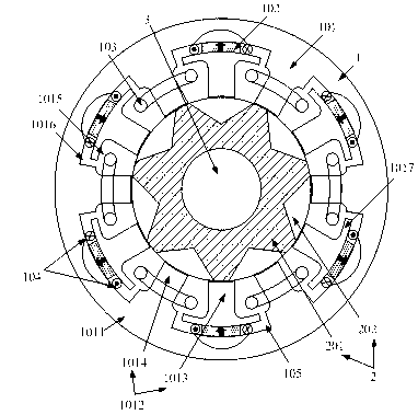
[0033] Such as figure 1As shown, a flux switching type internal permanent magnet memory motor of the present invention includes a casing, and a stator 1 , a rotor 2 and a rotating shaft 3 accommodated in the casing. The stator 1 is fixedly connected to the wall of the casing. The stator 1 is located outside the rotor 2 . The rotor 2 is a cylinder with through holes. The rotor 2 includes a segmented rotor core 202 and a star-shaped magnetic isolation block 201 with a central through hole. Both the rotating shaft 3 and the magnetic isolation block 201 are made of non-magnetic materials. For example, both the rotating shaft 3 and the magnetic isolation block 201 are made of aluminum, copper, or steel. The segmented rotor cores 202 are fan-shaped, and are uniformly distributed along the circumferential direction of the rotor 2 and f...


PUM


Abstract

The invention discloses a built-in permanent magnet memory motor of a magnetic flux switching type. The permanent magnet memory motor comprises a casing, a stator, a rotor and a rotating shaft, wherein the stator is a cylinder with a through hole and is formed by a star-shaped magnetic isolation block with a center through hole and partitioned rotor iron core discs; the rotating shaft is fixedly connected in the center through hole of the magnetic isolation block; and the partitioned rotor iron core discs are shaped like a fan and are uniformly distributed at the circumference of the rotor as well as fixedly connected to the outer surface of the magnetic isolation block. The stator comprises a stator iron core, permanent magnets, three-phase armature windings and pulse windings, wherein the stator iron core comprises a stator yoke and stator teeth formed by permanent teeth and armature teeth; the permanent magnets are shaped like a tile and radially magnetized, so that magnetic leakage factors are small; the magnetization directions of the two adjacent permanent magnets are opposite; the three-phase armature windings are wound on the armature teeth; and the pulse windings are wound on the permanent magnets. According to the permanent magnet memory motor, the weak magnetic ability and the rotation speed running range of the motor can be improved; and the no-load air gap magnetic field can be adjusted. In addition, the permanent magnet memory motor disclosed by the invention is strong in mechanical reliability, thereby being suitable for high-speed running.

Description

technical field [0001] The invention relates to an adjustable magnetic flux permanent magnet motor, in particular to a magnetic flux switching built-in permanent magnet memory motor. Background technique [0002] In the field of motors, due to the inherent characteristics of ordinary permanent magnet materials (such as NdFeB), the air gap magnetic field in the motor is basically kept constant, and the speed regulation range is very limited when operating as an electric motor. The application of wide-speed adjustable direct drive applications such as electric vehicles and aerospace is limited to a certain extent. Therefore, the adjustable flux permanent magnet motor aimed at realizing the effective adjustment of the air gap magnetic field of the permanent magnet motor has always been a hot spot and difficulty in the field of motor research. . Permanent magnet memory motor (hereinafter referred to as "memory motor") is a new type of flux controllable permanent magnet motor, w...

Claims


Application Information

Patent Timeline
Patent Type & Authority Applications(China)
IPC IPC(8): H02K21/02H02K1/17H02K1/22H02K1/16H02K3/12
Inventor 阳辉林鹤云颜建虎黄允凯房淑华壮而行张洋
Owner SOUTHEAST UNIV
Why Eureka
Try Eureka