
Magnetic fluid electric generator taking low-melting-point gallium alloy as electricity generating working medium

A magnetic fluid generator and magnetic fluid power generation technology, applied in electrical components, electromechanical devices, etc., can solve the problems of strong explosion, spontaneous combustion, limited use range, etc., and achieve high power density, simple and safe preparation, and improved operability. Effect

Inactive Publication Date: 2013-07-10
INST OF ELECTRICAL ENG CHINESE ACAD OF SCI
View PDF6 Cites 9 Cited by
  • Summary
  • Abstract
  • Description
  • Claims
  • Application Information

AI Technical Summary

Problems solved by technology

However, sodium-potassium alloys are very reactive and will spontaneously ignite when exposed to air for a long time and explode violently when exposed to water
Therefore, sodium-potassium alloy puts forward high requirements on the assembly environment and sealing performance of the power generation device, which limits its application range.

Method used


Image

  • Magnetic fluid electric generator taking low-melting-point gallium alloy as electricity generating working medium
  • Magnetic fluid electric generator taking low-melting-point gallium alloy as electricity generating working medium

Examples


Embodiment Construction

[0011] The present invention will be further described below in conjunction with specific embodiments and accompanying drawings.

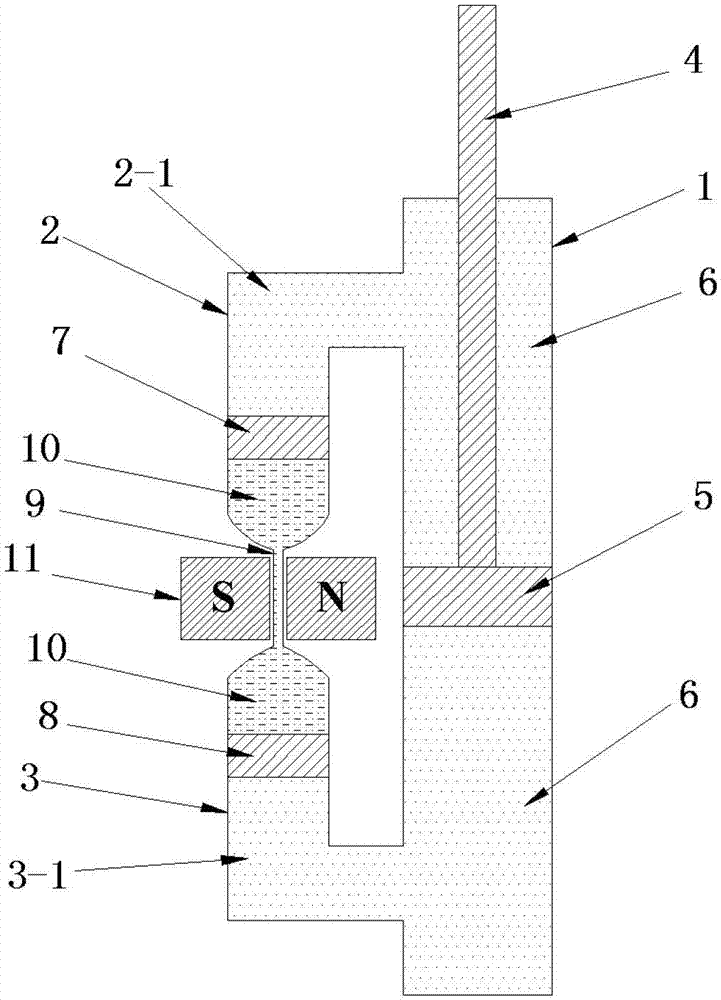
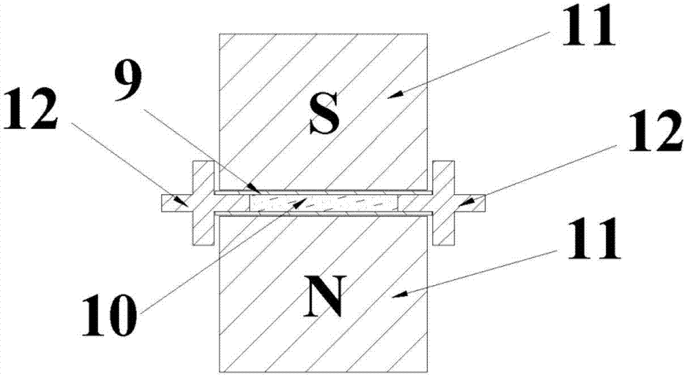
[0012] figure 1 It is a structural schematic diagram of the liquid magnetohydrogen generator of the present invention. The liquid metal magnetic fluid generator is mainly composed of the main hydraulic cylinder 1, the main piston 5, the main piston shaft 4, the upper and lower auxiliary hydraulic cylinders 2, 3, the magnet 11, the magnetic fluid power generation channel 9, a pair of flat electrodes 12, and the generator Quality 10, upper auxiliary piston 7, lower auxiliary piston 8 and hydraulic oil 6 are formed. The main piston 5 and the main piston shaft 4 are coaxially placed in the main hydraulic cylinder; the upper auxiliary piston 7 is placed in the auxiliary hydraulic cylinder 2, the lower auxiliary piston 8 is placed in the lower auxiliary hydraulic cylinder 3, the upper auxiliary piston 7 and the lower auxiliary piston 8 coaxial. One en...


PUM


Abstract

Provided is a magnetic fluid electric generator taking low-melting-point gallium alloy as an electricity generation working medium. A main piston (5) and a main piston shaft (4) are arranged in a main hydraulic cylinder (1) in a coaxial mode. An upper auxiliary piston (7) and a lower auxiliary piston (8) are respectively arranged in an upper auxiliary hydraulic cylinder (2) and a lower auxiliary hydraulic cylinder (3) in a coaxial mode. Two ends of the upper auxiliary hydraulic cylinder (2) and two ends of the lower auxiliary hydraulic cylinder (3) are respectively communicated with the main hydraulic cylinder (1) and a magnetic fluid electricity generating passage (9). The magnetic fluid electricity generating passage (9) penetrates through a magnetic hole of a magnetic body (11). A pair of flat type electrodes (12) are tightly stuck to the inner wall of the magnetic fluid electricity generating passage (9) in a symmetrical mode, and the inner wall of the magnetic fluid electricity generating passage (9) is parallel to a field direction. Hydraulic oil (6) is filled into the upper portion of the main hydraulic cylinder (1) and the upper portion (2-1) of the upper auxiliary hydraulic cylinder (2). The hydraulic oil (6) is filled into the lower portion of the main hydraulic cylinder (1) and the lower portion (3-1) of the lower auxiliary hydraulic cylinder (3). The electricity generation working medium (10) is filled into the communicated space between the upper auxiliary piston (7) and the lower auxiliary piston (8), and the electricity generation working medium (10) is the low-melting-point gallium alloy.

Description

technical field [0001] The invention relates to a liquid metal magnetic fluid generator. technical background [0002] US Patent No. 5473205 proposed a reciprocating liquid metal magnetohydrodynamic (LMMHD) automobile engine whose displacement can be changed according to the power requirements of the automobile, and started the research on the reciprocating LMMHD generator. The engine has 4 pistons with a dual-channel structure; free pistons at both ends of each channel seal the liquid metal; the inner piston that moves the liquid metal (liquid K or Na) is magnetically coupled to the outer piston that moves through the conventional internal combustion process. Alternating internal combustion strokes drive the liquid metal to reciprocate and linearly move in the MHD channel, cutting the magnetic field lines and generating AC power. Subsequently, reciprocating LMMHD generators began to be used in variable displacement automobile engines, distributed power supply and wave ener...

Claims


Application Information

Patent Timeline
Patent Type & Authority Applications(China)
IPC IPC(8): H02K44/08
Inventor 夏琦赵凌志彭爱武李建李然许玉玉沙次文
Owner INST OF ELECTRICAL ENG CHINESE ACAD OF SCI
Learn More