Porous implant material

A technology of implants and porous metals, applied in prosthesis, medical science, surgery, etc., can solve the problems of making implants close to human bones, and achieve the effects of avoiding stress shielding, easy access, and ensuring combination

Active Publication Date: 2013-07-10
MITSUBISHI MATERIALS CORP
View PDF6 Cites 5 Cited by
  • Summary
  • Abstract
  • Description
  • Claims
  • Application Information

AI Technical Summary

Problems solved by technology

Therefore, as described in these patent documents, it is difficult to prod

Method used


Image

  • Porous implant material
  • Porous implant material
  • Porous implant material

Examples


Example Embodiment

[0066] Example

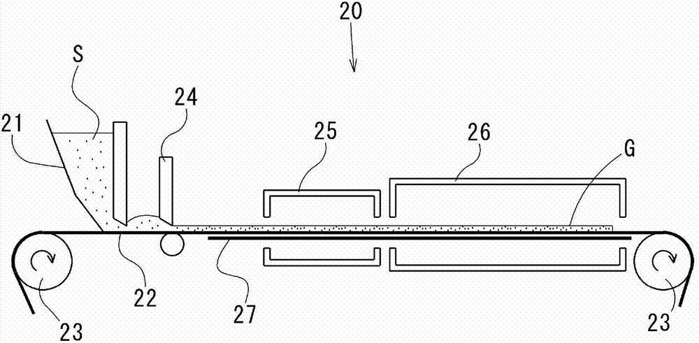
[0067] A green sheet was produced by the slurry foaming method, and a porous metal body was produced from the green sheet. Titanium metal powder (as a raw material), polyvinyl alcohol (as a binder), glycerin (as a plasticizer), alkylbenzene sulfonate (as a surfactant), heptane (as a Foaming agent) was kneaded with water as a solvent to prepare a slurry. The slurry is shaped into a plate shape and dried, and then a plurality of the green sheets are laminated, degreased and sintered, thereby obtaining a laminate of porous metal bodies.

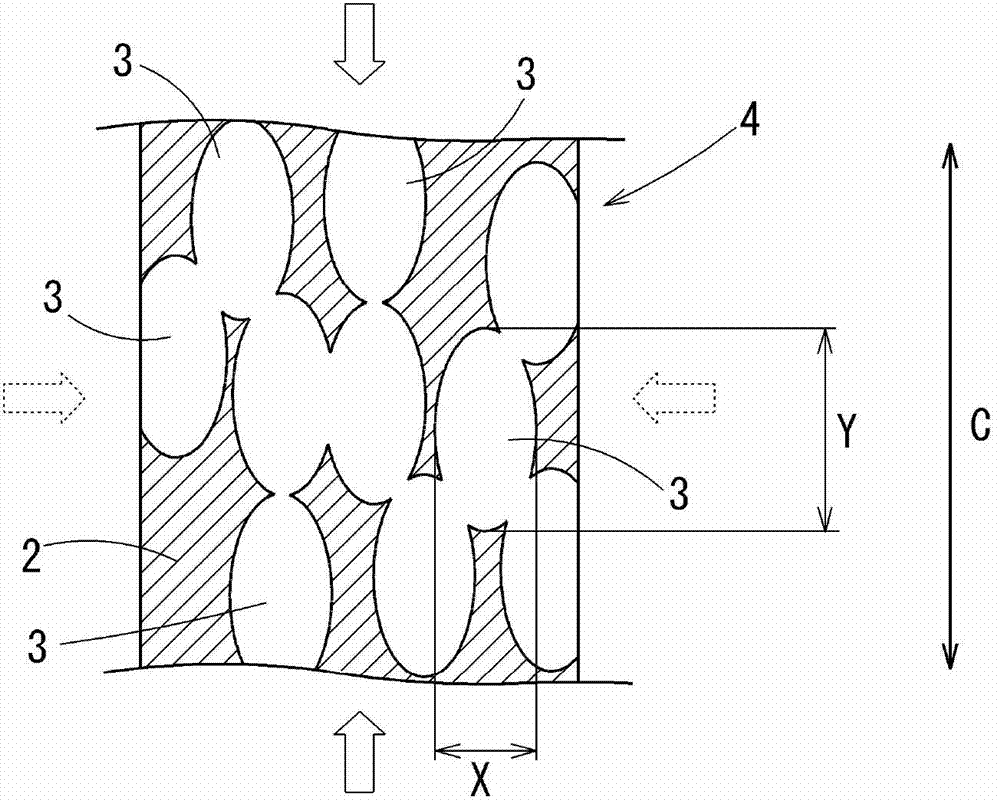
[0068] The laminated body of the porous metal body was compressed by a calender, and the surface and the cross section in the thickness direction were observed with an optical microscope.

[0069] Figure 4 Is the surface photo, Figure 5 It is a photo of the profile. As apparent from these figures, the pores opening on the surface are approximately circular, but the cross section is a flat shape squashed in the thickness direction....


PUM


Abstract

The invention has strength characteristics similar to human bone and ensures adequate bonding to bone even while avoiding the occurrence of stress shielding. It is obtained from a porous metal body having a three dimensional reticulated structure with multiple communicating pores (3) formed by a continuous backbone (2). The porosity is 50% to 92%. Each pore (3) is formed in a flat shape that is long in a direction parallel to the surface and short in the direction orthogonal to the surface and is formed so that the length Y of the pore (3) in a direction parallel to the surface is 1.2 times to 5 times the length X in the direction orthogonal to the surface. The strength when compressed in a direction parallel to the surface is 1.4 times to 5 times the strength when compressed in a direction orthogonal to the surface.

Description

technical field [0001] The present invention relates to a material used as an implant implanted into a living body, and in particular, to an implant material composed of a porous metal. [0002] this application claims priority based on Japanese Patent Application No. 2010-251430 for which it applied on November 10, 2010, and uses the content here. Background technique [0003] Implants described in Patent Documents 1 to 3 are available as implants used after being implanted in a living body. [0004] The implant (intervertebral spacer) described in Patent Document 1 is inserted and placed between the vertebral bodies after the intervertebral disc has been removed, and the upper surface of the spacer main body and the The lower surface forms a special shape. [0005] The implant (artificial dedendum) described in Patent Document 2 is composed of a solid columnar core material and a porous layer arranged on the side of the core material. The solid columnar core material is ...

Claims


Application Information

Patent Timeline
IPC IPC(8): A61L27/00
CPCA61L27/04A61L27/56A61L31/022A61L31/146
Inventor 太期雄三大森信一加藤公明
Owner MITSUBISHI MATERIALS CORP
Why Eureka
Try Eureka