Capacitive electromagnetic flowmeter

An electromagnetic flowmeter, capacitive technology, applied in the application of electromagnetic flowmeter to detect fluid flow, volume/mass flow generated by electromagnetic effects, measurement flow/mass flow, etc., can solve the problem that the excitation current of capacitive electromagnetic flowmeter cannot be further improved And other problems, to achieve the effect of increasing the excitation voltage

Active Publication Date: 2015-05-20
FUJIAN WIDE PLUS PRECISION INSTR
View PDF5 Cites 0 Cited by
  • Summary
  • Abstract
  • Description
  • Claims
  • Application Information

AI Technical Summary

Problems solved by technology

Since the operational amplifier, field effect tube and sampling resistor are used to realize the current source function, the operating voltage of the operational amplifier, the power consumption of the field effect tube and other parameters limit the increase of the excitation voltage and excitation current. The circuit generally uses an excitation voltage of no more than 36V Voltage, the output excitation current does not exceed 0.15A, and the excitation frequency is generally below 40Hz. The excitation current of the capacitive electromagnetic flowmeter cannot be further increased. Increasing the excitation frequency and reducing the differential interference and the same direction interference restrict the improvement of the signal-to-noise ratio of the sensor.

Method used


Image

  • Capacitive electromagnetic flowmeter
  • Capacitive electromagnetic flowmeter
  • Capacitive electromagnetic flowmeter

Examples


Embodiment Construction

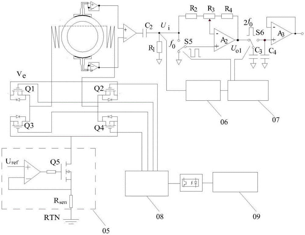
[0041] like Figure 4 or Figure 5 As shown, the capacitive electromagnetic flowmeter includes a capacitive sensor 1, a pre-op amplifier circuit 11, a flow signal processing circuit 10, a full-bridge inverter circuit 6, a full-bridge drive circuit 8, and an excitation current feedback circuit 7, as shown The excitation current feedback circuit 7 includes a first excitation current feedback circuit 7A, a second excitation current feedback circuit 7B and a timing control circuit 9;

[0042] The capacitive sensor includes a lining layer 1A, the outer wall of the lining layer is uniformly provided with a first detection electrode 2A, a second detection electrode 2B, a first excitation coil 4A and a second excitation coil 4B, and the first The detection electrode 2A is arranged opposite to the second detection electrode 2B, the first excitation coil 4A and the second excitation coil 4B are oppositely arranged, and the first detection electrode 2A and the second detection electrode...


PUM


Abstract

The invention relates to a capacitive electromagnetic flowmeter. A sensor of the capacitive electromagnetic flowmeter comprises a high-dielectric-constant industrial ceramic liner and a non-contact plated metal detecting sheet electrode. The sensor is provided with two opposite excitation coils serially connected to excite the inside of the sensor. The metal detecting electrode and a metal shielding electrode are connected to input and output ends of an operational preamplifier respectively to allow for equipotential shielding. A timing control circuit controls a switch of a full-bridge inverter circuit and an analog switch of a flow signal processing circuit according to logic signals of exciting current so as to control the exciting current in the coils and process the flow signals. The full-bridge inverter circuit is capable of enhancing the exciting current to increase the signal-to-noise ratio of the flow signals while inhibiting differential disturbing influence. The full-bridge inverter circuit is used with the timing control circuit to centrally control the power switch of the inverter circuit and the analog switch of the flow signal processing circuit, differential disturbance in the flow signals are removed accurately, and reliable detection on fluid flow is realized finally.

Description

technical field [0001] The invention relates to an electromagnetic flowmeter, in particular to a capacitive electromagnetic flowmeter with a higher signal-to-noise ratio. Background technique [0002] The DC power supply provides rectangular wave excitation current to the coil through the full-bridge inverter circuit to form an electromagnetic field. The fluid flowing in the measuring tube cuts the magnetic force line to generate an induced electromotive force, which is proportional to the fluid flow rate. Since the exciting current is alternating, the induced potential generated is also alternating, and its frequency is the same as that of the exciting current. A pair of electroplated sheet metal electrodes are set on the outer wall of the insulating ceramic measuring tube. The electrode plate and the fluid form a capacitance with the measuring tube wall as the medium. The induced potential is coupled to the detection electrode by using the capacitance-to-alternating signal...

Claims


Application Information

Patent Timeline
Patent Type & Authority Patents(China)
IPC IPC(8): G01F1/58G01F1/60
Inventor 陈英华邹崇周永宏黄训松王剑凌胡国清
Owner FUJIAN WIDE PLUS PRECISION INSTR
Why Eureka
Try Eureka