
DC (direct control) servo drive control system

A technology of DC servo and drive control, which is applied in the direction of control system, DC motor speed/torque control, excitation or armature current control, etc. Problems such as the deterioration of the system effect, to achieve the effect of strong resistance to motor parameters and load disturbance, satisfying the amount of calculation, and fast operation speed

Inactive Publication Date: 2013-07-17
INST OF ELECTRICAL ENG CHINESE ACAD OF SCI
View PDF6 Cites 17 Cited by
  • Summary
  • Abstract
  • Description
  • Claims
  • Application Information

AI Technical Summary

Problems solved by technology

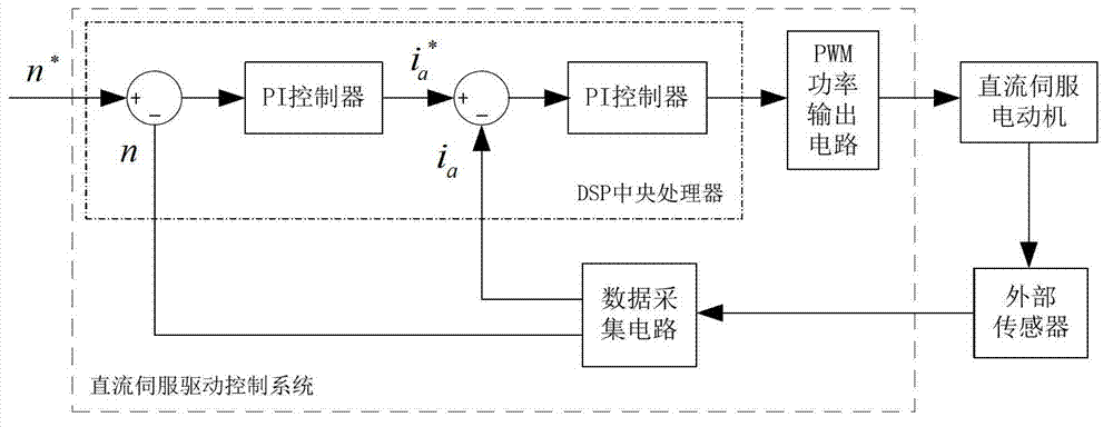
Such a control system structure can meet the requirements of high steady-state precision and fast dynamic response, but it lacks a certain anti-disturbance ability in terms of control system effect deterioration caused by factors such as controlled object parameter disturbances and load fluctuations.
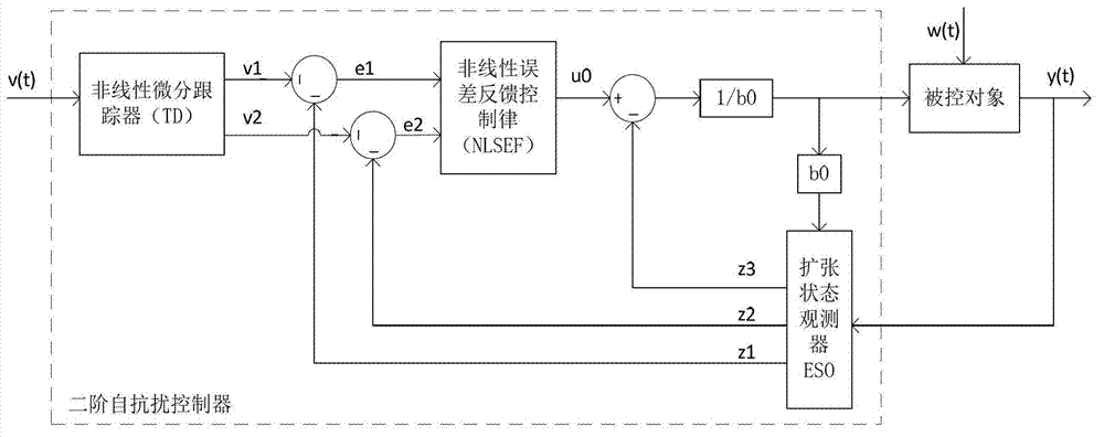
[0004] Chinese patents CN201039069Y, CN102811015A and CN101499769A, and "DC Double Closed-loop Speed ​​Regulation System Based on Active Disturbance Rejection Controller" (Xu Han, Xu Yu, Liu Dejun. [J]. Chemical Technology, 2004, 06(12): 42-44 ) The main idea is to apply the ADRC controller directly or after simplified transformation to the control system, which has the characteristics of fast response speed and strong anti-disturbance ability. Most of the control objects are AC motors or excitation devices, etc. A few articles involve DC motors The articles only stay at the stage of simulation research, and seldom involve the practical application of DC servo drive control system with high performance requirements.

Method used


Image

  • DC (direct control) servo drive control system
  • DC (direct control) servo drive control system
  • DC (direct control) servo drive control system

Examples


Embodiment Construction

[0025] The present invention will be further described below in conjunction with the accompanying drawings and specific embodiments.

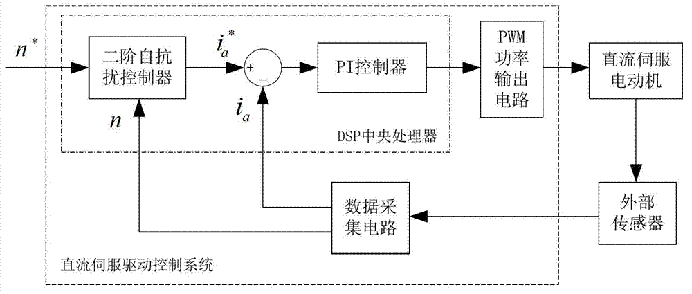
[0026] figure 1It is the DC servo drive control system based on the active disturbance rejection controller of the present invention. The system is mainly composed of data acquisition circuit, DSP central processing unit and PWM power output circuit. The input terminal of the DSP central processor of the DC servo drive control system based on the active disturbance rejection controller receives the speed given value of the host computer (such as PLC or computer) and the DC servo motor speed feedback value and current fed back by the external sensor. The feedback value is output to the PWM power output circuit after being processed by the DSP central processor, and the output terminal of the PWM power output circuit is connected to the DC servo motor which is the control object of the DC servo drive control system. The input end of the data a...


PUM


Abstract

An DC servo drive control system consists of a data acquisition circuit, a DSP (Digital Signal Processor) CUP (central processing unit) and a PWM (Pulse-Width Modulation) power output circuit, wherein the DSP CUP includes a second order active-disturbance-rejection controller and a PI (proportional-integral) controller. The input end of the DSP CUP receives a velocity set value sent by an upper computer and an DC servo-motor velocity feedback value and a current feedback value which are sent by an external sensor in a feedback mode, and the velocity set value, the DC servo-motor velocity feedback value and the current feedback value are output to the PWM power output circuit after being processed by the DSP CUP; and the output end of the PWM power output circuit is connected with an DC servo-motor which is the controlled object of the DC servo drive control system. The input end of the data acquisition circuit is connected with the external sensor, the output end of the data acquisition circuit is connected with the input end of the DSP CUP, the data of the DC servo-motor collected by the external sensor are transmitted to the PWM power output circuit after being sent to the DSP CUP for being processed through the data acquisition circuit, and the WM power output circuit outputs control signals to control the DC servo-motor.

Description

technical field [0001] The invention relates to a DC servo drive control system based on an active disturbance rejection controller. Background technique [0002] The DC servo drive system in some applications requires the control system to have the characteristics of fast dynamic response, high stability and precision, and strong resistance to load and parameter disturbance, such as the electric pitch servo drive system of wind turbines. In the servo drive system, the resistance value and inductance value of the armature winding of the executive motor are easily affected by temperature, and the motor parameters provided by different manufacturers are also different. The influence of these factors will reduce the performance of the conventional PID closed-loop control system. Although conventional PID controllers can meet the requirements of high steady-state precision and fast dynamic response, they are poor in anti-disturbance ability of load and motor parameters. [0003...

Claims


Application Information

Patent Timeline
IPC IPC(8): H02P7/00H02P7/29
Inventor 汪常明胡书举张雷夏安俊赵斌许洪华
Owner INST OF ELECTRICAL ENG CHINESE ACAD OF SCI
Learn More