Engine exhaust gas purification device

An exhaust gas purification device and engine technology, which is applied to exhaust devices, engine components, combustion engines, etc., to achieve high reliability and durability

Active Publication Date: 2013-07-17
MITSUBISHI HEAVY IND LTD +1
View PDF5 Cites 13 Cited by
  • Summary
  • Abstract
  • Description
  • Claims
  • Application Information

AI Technical Summary

Problems solved by technology

Therefore, the electric power required to drive the electric blower is required, although it is not as high as high-voltage EGR, but in

Method used


Image

  • Engine exhaust gas purification device
  • Engine exhaust gas purification device

Examples


Embodiment Construction

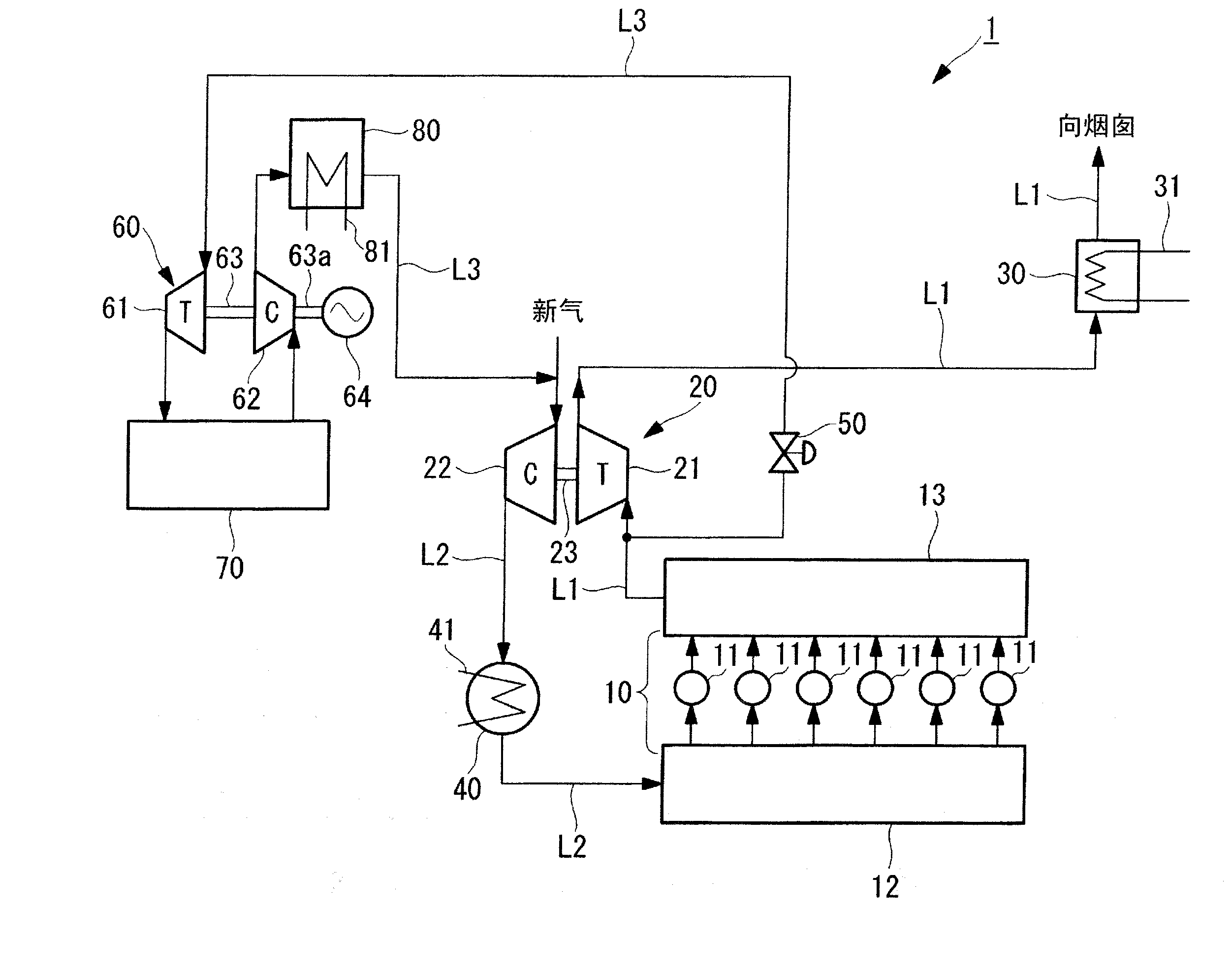
[0029] Hereinafter, regarding the engine exhaust gas purification device of the present invention, based on figure 1 , to describe the first embodiment. It should be noted, figure 1 The schematic configuration diagram of the engine exhaust gas purifying device shown is a configuration example mainly incorporated into the main engine intake and exhaust system serving as the main engine of the ship.

[0030] figure 1 The shown engine exhaust gas purification device (hereinafter referred to as "purification device") 1 is to remove harmful sulfur oxides or nitrogen oxides, etc. A device for reducing and removing substances (air pollutants).

[0031] A main engine 10 for propulsion of a ship is mounted in the ship, and exhaust gas discharged from the main engine 10 is discharged to the atmosphere through a funnel.

[0032] The main engine 10 includes a plurality of cylinders 11 , an air supply manifold 12 , and an exhaust manifold 13 . Fuel supplied from a fuel supply system n...


PUM


Abstract

Provided is an engine exhaust gas purification device which reduces or eliminates the need for electric power required to raise the pressure of EGR gas, which is extracted from the upstream side from an exhaust turbosupercharger in order to be used for exhaust gas recirculation (EGR), after cleaning treatment by an exhaust gas cleaning unit. An engine exhaust gas purification device (1) for reducing or eliminating air pollutants in exhaust gas emitted from a main engine (10) provided with an exhaust turbosupercharger (20) is provided with an exhaust gas cleaning unit (70) for subjecting part of exhaust gas introduced as EGR gas from an exhaust system (L1) on the upstream side from a turbine part (21) of the exhaust turbosupercharger (20) to cleaning treatment, and a recirculation exhaust turbosupercharger (60) for raising the pressure of the EGR gas which has passed through the exhaust gas cleaning unit (70) by a recirculation compressor part (62) coaxial with a recirculation turbine part (61) disposed on the upstream side from the exhaust gas cleaning unit (70) and driven using the EGR gas.

Description

technical field [0001] The present invention relates to an engine exhaust gas purifying device applied to, for example, a marine main engine (main engine) diesel engine or the like. Background technique [0002] Diesel engines serving as main engines for ships are in a situation where exhaust gas regulations related to sulfur oxides (SOx) and nitrogen oxides (NOx) applicable to ships are being strengthened. [0003] Exhaust gas recirculation (EGR: Exhaust Gas Recirculation) is known as a technique for reducing nitrogen oxides generated from a diesel engine. This exhaust gas recirculation (hereinafter referred to as "EGR") takes part of the exhaust gas after combustion and guides it to the air supply side to re-supply the exhaust gas. High-pressure EGR and low-pressure EGR are known. [0004] As conventional technologies related to EGR, there is a configuration including an exhaust gas cleaning device called a scrubber as in Patent Documents 1 and 2 below, for example. In a...

Claims


Application Information

Patent Timeline
IPC IPC(8): F02M25/07F02B37/00F02B41/10
CPCY02T10/166F02M25/0727F02M25/0739F02M25/071F02B37/18F02M25/074Y02T10/121Y02T10/144F02B61/04F02G5/02F02B37/001F02M26/07F02M26/23F02M26/34F02M26/35Y02T10/12F01N3/04F02B37/00F02B41/10
Inventor 村田聪樋口纯
Owner MITSUBISHI HEAVY IND LTD
Why Eureka
Try Eureka