Belt chip cleaning device

A cleaning device and cutting chip technology, which is applied in the direction of metal processing machinery parts, maintenance and safety accessories, metal processing equipment, etc., can solve the problems of easy agglomeration and cannot fundamentally solve the problem of cutting chip accumulation, so as to avoid cutting chips caking effect

Active Publication Date: 2016-01-13
徐州帝伦木业有限公司
View PDF8 Cites 0 Cited by
  • Summary
  • Abstract
  • Description
  • Claims
  • Application Information

AI Technical Summary

Problems solved by technology

[0005] The purpose of the present invention is to overcome the deficiency that the existing technology cannot fundamentally solve the problem of chip accumulation and the defect that it is easy to agglomerate, and provides a chip collection device

Method used


Image

  • Belt chip cleaning device
  • Belt chip cleaning device
  • Belt chip cleaning device

Examples


Embodiment 1

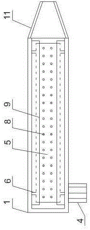
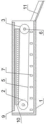
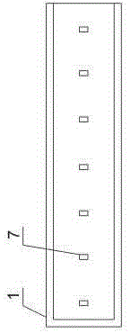
[0036] Such as figure 1 , figure 2 and image 3 As shown, the belt-type chip cleaning device includes a housing 1, a driving pulley 2, a driven pulley 3, a motor 4, a belt 5 and a rotating shaft 6, the top of the housing 1 is open, and one end of the housing 1 is open. The pulley 2 and the driven pulley 3 are fixed in the casing 1 through the rotating shaft 6, the driving pulley 2 is close to the closed end of the casing 1, the driven pulley 3 is close to the open end of the casing 1, and the motor 4 is arranged in the casing Outside the body 1, the rotating shaft 6 connected with the driving pulley 3 is connected with the output shaft of the motor 4, the belt 5 is sleeved on the driving pulley 2 and the driven pulley 3, and the bottom of the housing 1 is provided with an oil leakage hole 7.

[0037] This embodiment is set on both sides of the milling platform, and the cutting chips generated during the milling process will automatically fall on the belt 5, and the cutting ...

Embodiment 2

[0040] Such as figure 1 As shown, in this embodiment, on the basis of the above-mentioned embodiments, the belt 5 is provided with an oil seepage hole 8, and the diameter of the oil seepage hole 8 is 1 mm.

[0041] The oil seepage hole 8 can prevent cooling fluid and cooling oil from accumulating on the belt 5, and can avoid the occurrence of agglomeration of fine cutting chips on the belt 5. The diameter of the oil seepage hole 8 is 1mm, which can prevent the cutting chips on the belt 5 from leaking into the housing 1 from the belt 5, and avoid the trouble of cleaning the housing 1.

Embodiment 3

[0043] Such as figure 1 and figure 2 As shown, on the basis of the above embodiments, this embodiment also includes a brush 10, the top of both sides of the housing 1 is provided with an inwardly extending flange 9, and the brush 10 is vertically fixed on the flange 9 Above, the brush 10 is in contact with the outer surface of the belt 5 .

[0044] The brush 10 can prevent the cutting chips on the belt 5 from falling into the housing 1 from both sides of the belt 5 without hindering the movement of the belt 5 , avoiding the accumulation of cutting chips in the housing 1 .


PUM


Abstract

The invention discloses a belt type cutting chip cleaning device comprising a shell body, a driving belt wheel, a driven belt wheel, a motor, a belt and a rotary shaft, wherein the top of the shell body is open, one end of the shell body is open, the driving belt wheel and the driven belt wheel are fixed in the shell body through the rotary shaft, the driving belt wheel is close to the closed end of the shell body, the driven belt wheel is close to the open end of the shell body, the motor is arranged outside the shell body, and a rotary shaft connected with connected with the driving belt wheel is connected with an output shaft of the motor, the belt is sleeved on the driving belt wheel and the driven belt wheel, and an oil leakage hole is formed at the bottom of the shell body. The belt type cutting chip cleaning device has the advantages that the cutting chip accumulation problem which can not be fundamentally solved in the prior art is solved, human power is not needed in a whole process, the two sides of a milling platform can be kept clean all the time, the problem that cutting chip accumulation affects normal processing is solved, the oil leakage hole is formed at the bottom of the shell body, cooling liquid and cooling oil can be prevented from being mixed with cutting chips, and the problem of caking of the cutting chips is solved.

Description

technical field [0001] The invention relates to the field of milling, in particular to a belt-type chip cleaning device for a milling machine. Background technique [0002] A milling machine is a device that processes the surface of a workpiece fixed on a milling platform through the movement of a milling cutter. According to the processing characteristics of the milling machine, a large amount of cutting chips will be generated during the milling process, especially for large workpieces. If the cutting chips are not cleaned, a large amount of cutting chips will accumulate on both sides of the milling platform, which will hinder normal processing. [0003] At present, the more commonly used method is to set chip collection grooves on both sides of the milling machine, and the chips generated during the milling process will fall into the chip collection grooves, and then be cleaned manually. The disadvantage of this approach is that it still relies on manpower and requires ...

Claims


Application Information

Patent Timeline
Patent Type & Authority Patents(China)
IPC IPC(8): B23Q11/00
Inventor 王曾勇叶礼
Owner 徐州帝伦木业有限公司
Why Eureka
Try Eureka