Vehicle suspension system and vehicle with same
A vehicle suspension and axle technology, which is applied in the field of vehicles and vehicle suspension systems, can solve the problems that the floor cannot achieve one step, the standing area is small, and the passenger passage is narrow.
- Summary
- Abstract
- Description
- Claims
- Application Information
AI Technical Summary
Problems solved by technology
Method used
Image
Examples
Embodiment 1
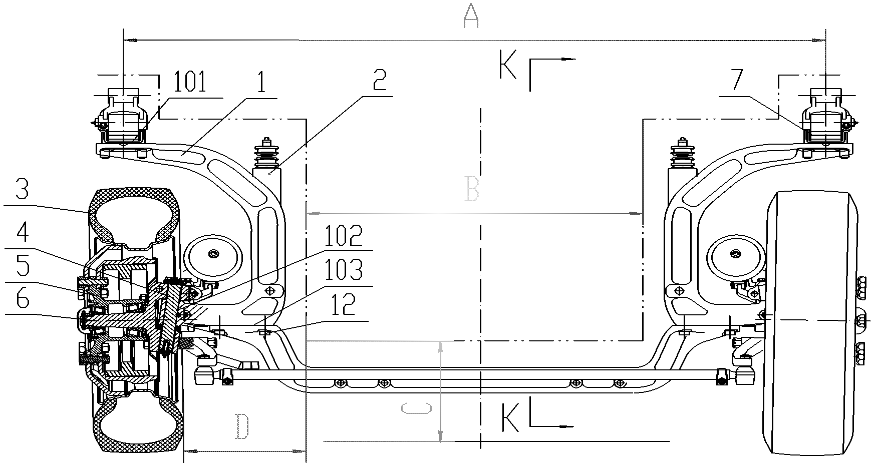
[0055] Such as image 3 , Figure 4 and Figure 5 As shown, the suspension system in this embodiment is a non-independent form. The front axle 1 adopts a segmented structure process, which is disconnected at the division plane 103 and connected as a whole by bolts 12, which can reduce the tonnage of the forging equipment and the mold size. Both sides of the front axle 1 are "C"-shaped beam structures, the upper end of the "C"-shaped beam structure is provided with a supporting surface 101 for elastic elements, and the lower end is provided with a kingpin mounting hole 102, and the middle section of the front axle is a large drop structure, so that the middle section of the front axle A large drop is formed between the upper surface and the wheel axis, and the depth of the drop structure is set to enable the floor of the vehicle passage to realize a step. The specific form of the elastic element 7 in this embodiment is a leaf spring, which is installed on the upper end suppo...
Embodiment 2
[0058] Such as Figure 6 As shown, the front axle 1 is integrally formed by an integral structure process. Other structures in this embodiment are the same as those in Embodiment 1, and will not be described again here.
Embodiment 3
[0060] Such as Figure 7 and Figure 8 As shown, in the present embodiment, the suspension form is independent, and the "C" beam structures on the left and right sides of the front axle 1 are independent of each other, and there is no middle section of the front axle in the middle. The "C" beam structure on each side is attached to the carriage separately. In this case, the elastic element 7 is embodied in the present example as an air spring. The guide element 9 is no longer Figure 5 Instead, it includes an upper A-arm 901 and a lower A-arm 902, and the "C"-shaped beam structure on each side passes through the upper and lower A-arms 901 and 902 respectively at its upper and lower positions. Connect to the carriage. Other structures in this embodiment are the same as those in Embodiment 1, and will not be described again here.
PUM
 Abstract
Description
Claims
Application Information
 - R&D
- Intellectual Property
- Life Sciences
- Materials
- Tech Scout
- Unparalleled Data Quality
- Higher Quality Content
- 60% Fewer Hallucinations
Browse by: Latest US Patents, China's latest patents, Technical Efficacy Thesaurus, Application Domain, Technology Topic, Popular Technical Reports.
© 2025 PatSnap. All rights reserved.Legal|Privacy policy|Modern Slavery Act Transparency Statement|Sitemap|About US| Contact US: help@patsnap.com


