Hydraulic power device of bear-loading hopping robot

A hydraulic power device, robot technology, applied in the direction of motor vehicles, mechanical equipment, transportation and packaging, etc., can solve the problems of small power/mass ratio, poor load-bearing capacity, complex robot leg structure, etc.

Inactive Publication Date: 2013-07-24
NORTHWESTERN POLYTECHNICAL UNIV
View PDF3 Cites 10 Cited by
  • Summary
  • Abstract
  • Description
  • Claims
  • Application Information

AI Technical Summary

Problems solved by technology

The disadvantage of this method is that the power/mass ratio is small and the load-bearing capacity is poor. In addition to the miniatur

Method used


Image

  • Hydraulic power device of bear-loading hopping robot
  • Hydraulic power device of bear-loading hopping robot
  • Hydraulic power device of bear-loading hopping robot

Examples


Embodiment Construction

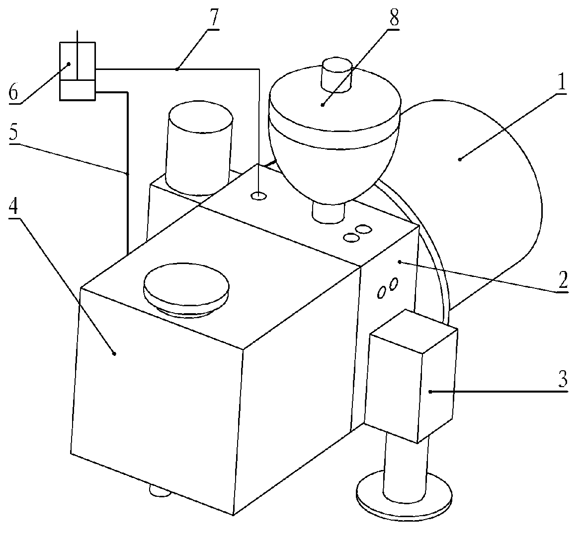
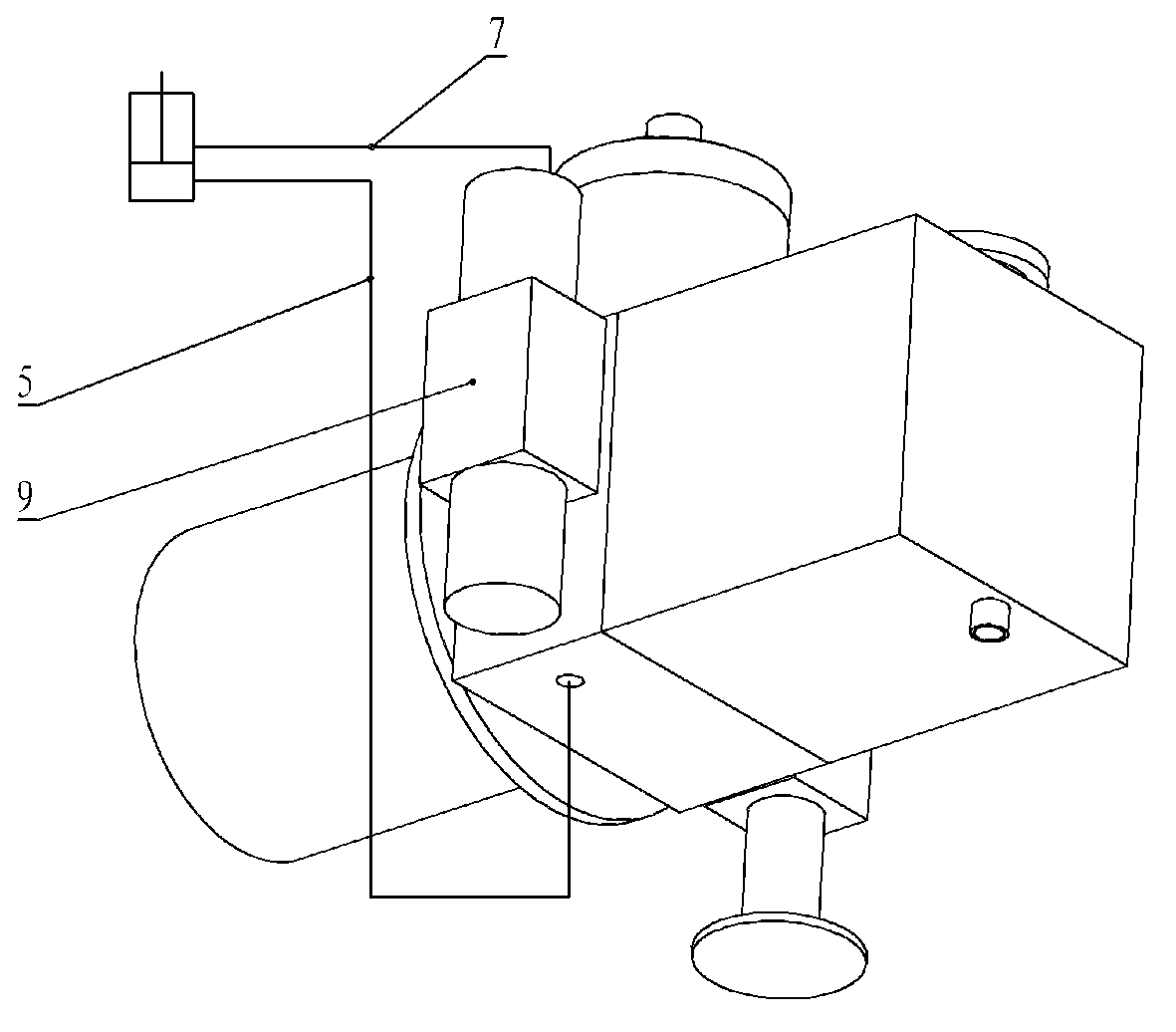
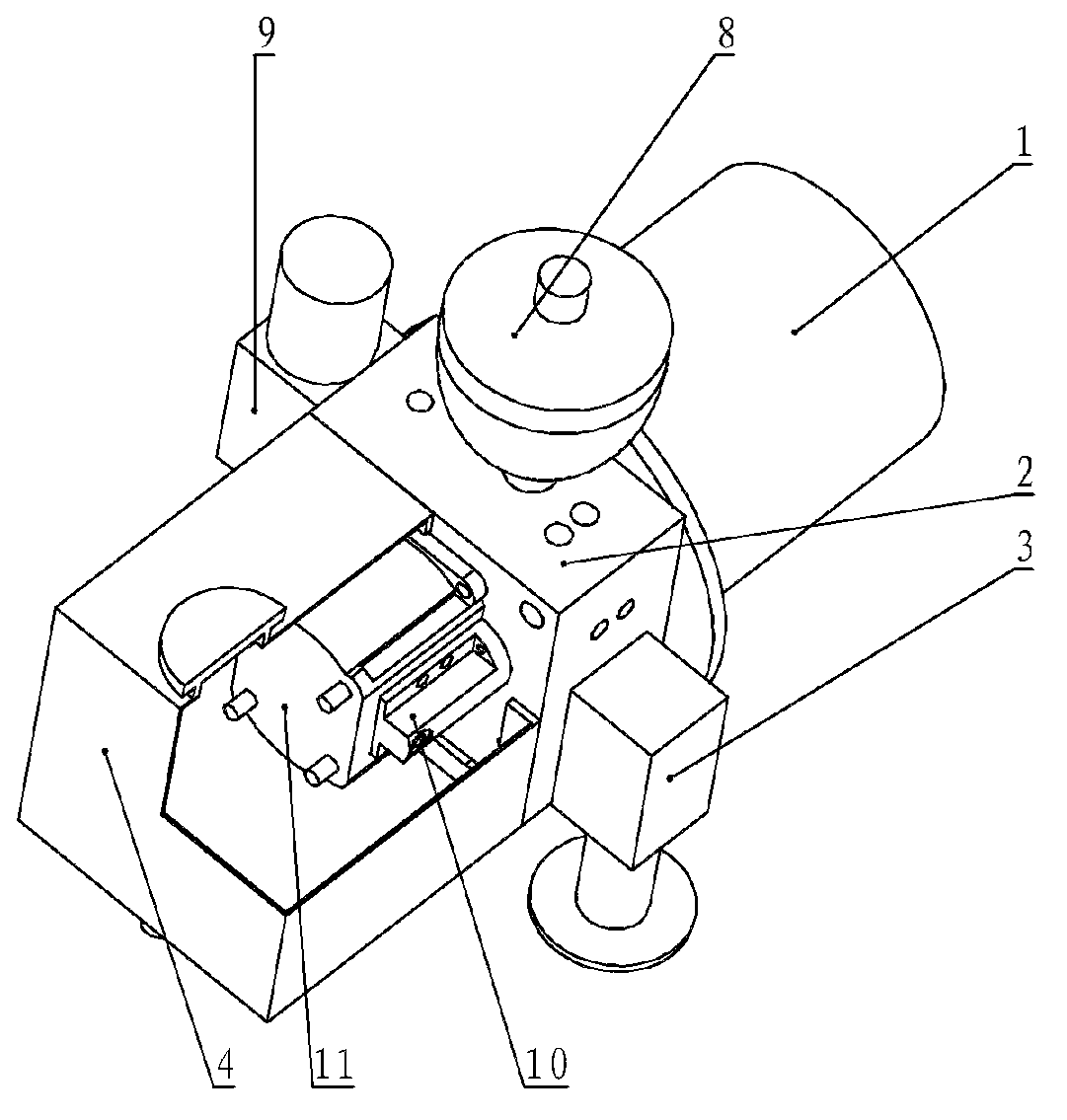
[0019] This embodiment is a hydraulic power device for a load-bearing bouncing robot.

[0020] refer to figure 1 , figure 2 , image 3 , Figure 4 , the hydraulic power device of the load bouncing robot of the present invention adopts the hydraulic integrated block mode; the oil circuit integrated block 2 is equipped with a motor 1, an overflow valve 3, a fuel tank 4, an accumulator 8, a reversing valve 9, an oil guide block 10, and a gear Pump 11, coupling 12, first hydraulic pipe 5 and second hydraulic pipe 7; the oil port of each hydraulic component is matched with the oil hole on the installation surface of the corresponding oil circuit manifold 2; the hydraulic pipe The other end of the hydraulic cylinder 6 is connected to the hydraulic cylinder 6, which is the power actuator; the hydraulic cylinder 6 is fixedly installed at the joints of the robot to provide power for the joint movement of the robot. The oil circuit manifold 2 is located at the center of the hydraul...


PUM


Abstract

The invention relates to a hydraulic power device of a bear-loading hopping robot. A hydraulic manifold block form is applied. A motor, an energy accumulator, a reversing valve, an overflow valve, an oil tank, an oil guiding block, a gear pump and a hydraulic pipeline are installed on an oil way manifold block, wherein the oil guiding block and the gear pump are fixed in the oil tank. An oil port of a hydraulic element is connected with a corresponding oil port on the oil way manifold block. The other end of the hydraulic pipeline is connected with a hydraulic cylinder. The motor is connected with the gear pump through a coupler. When the motor operates, the gear pump injects oil in the oil tank into a corresponding oil way in the oil way manifold block through the oil guiding block, the energy accumulator accumulates energy, the flow direction inside the hydraulic pipeline is controlled through the reversing valve, and quick movements of the hydraulic cylinder are achieved. The hydraulic power device of the bear-loading hopping robot is small in size, low in weight, high in ratio of power to mass, easy to control, capable of providing system power for assigned joints in a centralized mode in an extremely short time, and capable of meeting driving requirements of special movements, thereby enabling the overall structure of the bear-loading hopping robot to be simple and compact.

Description

technical field [0001] The invention relates to a power device of a bouncing robot, in particular to a hydraulic power device of a weight-bearing bouncing robot. Background technique [0002] The bouncing robot works in complex terrain, and has broad application prospects in military material transportation, field exploration and exploration, and interstellar exploration. Especially in interstellar exploration, jumping robots can carry a variety of detection instruments and acquisition equipment, cross uneven objects on the surface of the planet, automatically bypass obstacles and complex terrain, and complete various exploration tasks; in addition, in interstellar exploration, due to the moon and The gravitational acceleration on the surface of Mars is much lower than that of the earth, and the jumping motion can make full use of its own advantages. [0003] At present, in terms of bouncing robot research, Case Western Reserve University of the United States has developed ...

Claims


Application Information

Patent Timeline
IPC IPC(8): B62D57/02F15B1/02
Inventor 葛文杰同新星徐升谈效龙火统龙
Owner NORTHWESTERN POLYTECHNICAL UNIV
Why Eureka
Try Eureka