
High-speed optical fiber drawing device and method

An optical fiber, high-speed technology, applied in the field of high-speed optical fiber drawing devices, can solve the problems of large variation in optical fiber diameter, strong optical fiber jitter, easy reduction of optical fiber warpage, etc., to achieve stable warpage, uniform stress distribution, Guaranteed quality effect

Active Publication Date: 2013-07-24
FENGHUO COMM SCI & TECH CO LTD
View PDF12 Cites 17 Cited by
  • Summary
  • Abstract
  • Description
  • Claims
  • Application Information

AI Technical Summary

Problems solved by technology

From theoretical analysis, when the drawing speed of the optical fiber is increased from 1000m / min to 2500m / min, the centrifugal force of the optical fiber drawn at the speed of 2500m / min is more than 6 times that of the optical fiber drawn at the speed of 1000m / min, but in In actual situations, even if the drawing speed of the optical fiber reaches 2500m / min, since the optical fiber will turn when it passes the steering wheel, and the steering wheel is the turning point of the optical fiber path, the centrifugal force generated by the optical fiber passing through the steering wheel will cause the optical fiber to vibrate strongly, and the optical fiber jitters Afterwards, it will deviate from the correct course of action, thereby reducing
[0007] To sum up, if a large-size optical fiber preform is used for high-speed drawing, the diameter of each part of the optical fiber will vary greatly, the warpage of the optical fiber will easily decrease, and it is difficult to ensure the coating quality of the optical fiber and the quality of the optical fiber itself.

Method used


Image

  • High-speed optical fiber drawing device and method
  • High-speed optical fiber drawing device and method

Examples


Embodiment 1

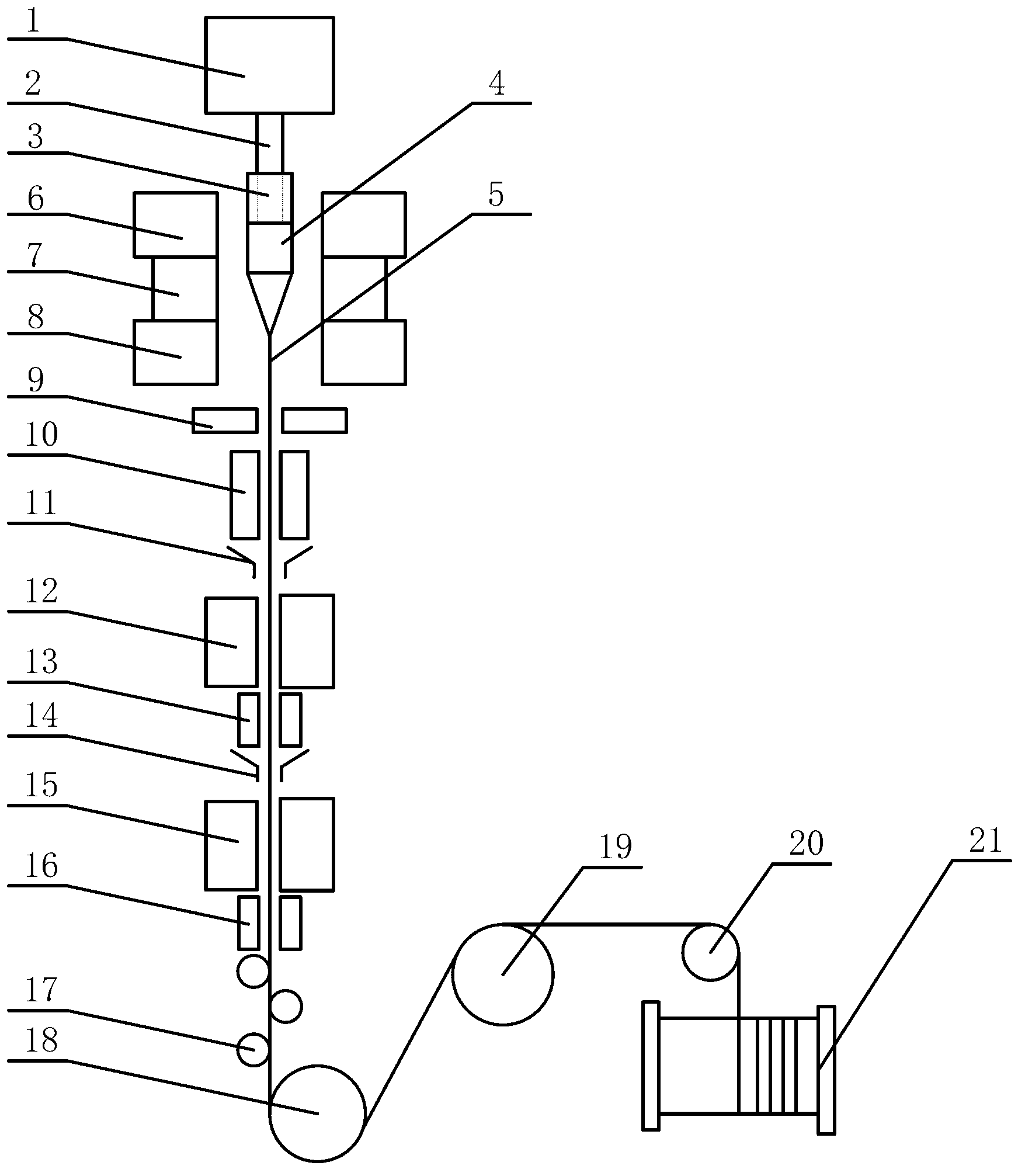
[0053] Embodiment 1: An optical fiber preform rod 4 with a diameter of 150 mm and a tail rod 2 with a diameter of 60 mm are selected, and the drawing speed is 2200 m / min.

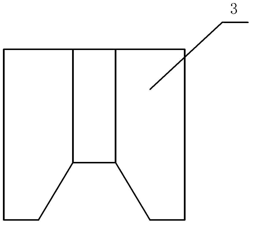
[0054] Put the tail rod 2 on the top of the optical fiber preform 4 through the quartz collar 3, the inner diameter of the quartz collar 3 is 62 mm, and the outer diameter 21 is 150 mm; hang the top of the tail rod 2 on the bottom of the hanging rod mechanism 1. The optical fiber preform 4 and the tail rod 2 covered with the quartz collar 3 move at a speed of 2200m / min, passing through the preheating mechanism 6, the melting mechanism 7 and the annealing mechanism 8 in sequence, the value of a:b is 1.0, and the value of c:b The value is 1.0; the temperature of the preheating mechanism 6 is set at 1350°C, and the preheating mechanism 6 preheats the optical fiber preform 4 and tail rod 2; the temperature of the melting mechanism 7 is set at 1850°C to 2200°C, and the melting The mechanism 7 melts and draws the...

Embodiment 2

[0059] Embodiment 2: An optical fiber preform 4 with a diameter of 120 mm and a tail rod 2 with a diameter of 50 mm are selected, and the drawing speed is 2300 m / min.

[0060] Pass the tail rod 2 at the top of the optical fiber preform 4 through the quartz collar 3, the inner diameter of the quartz collar 3 is 52 mm, and the outer diameter 21 is 120 mm; hang the top of the tail rod 2 on the bottom of the hanging rod mechanism 1. The optical fiber preform 4 and the tail rod 2 covered with the quartz collar 3 move at a speed of 2300m / min, and pass through the preheating mechanism 6, the melting mechanism 7 and the annealing mechanism 8 in sequence, the value of a:b is 0.5, and the value of c:b The value is 0.5; the temperature of the preheating mechanism 6 is set at 1200°C, and the preheating mechanism 6 preheats the optical fiber preform 4 and tail rod 2; the temperature of the melting mechanism 7 is set at 1800°C to 2100°C, and the melting The mechanism 7 melts and draws the p...

Embodiment 3

[0065] Embodiment 3: An optical fiber preform 4 with a diameter of 150 mm and a tail rod 2 with a diameter of 60 mm are selected, and the drawing speed is 2400 m / min.

[0066] Put the tail rod 2 on the top of the optical fiber preform 4 through the quartz collar 3, the inner diameter of the quartz collar 3 is 62 mm, and the outer diameter 21 is 150 mm; hang the top of the tail rod 2 on the bottom of the hanging rod mechanism 1. The optical fiber preform 4 and the tail rod 2 covered with the quartz collar 3 move at a speed of 2400m / min, and pass through the preheating mechanism 6, the melting mechanism 7 and the annealing mechanism 8 in sequence, the value of a:b is 1.0, and the value of c:b The value is 1.0; the temperature of the preheating mechanism 6 is set at 1350°C, and the preheating mechanism 6 preheats the optical fiber preform 4 and tail rod 2; the temperature of the melting mechanism 7 is set at 1850°C to 2200°C, and the melting The mechanism 7 melts and draws the pr...


PUM


Abstract

The invention discloses a high-speed optical fiber drawing device and method which relate to the field of optical fiber communication. The method comprises steps of: preheating an optical fiber perform which is sleeved with a quartz lantern ring through a preheating mechanism; melting and drawing the optical fiber perform through a melting mechanism so as to form an optical fiber; annealing the optical fiber through an annealing mechanism; coating the optical fiber through a first coating device, curing the coating through a first coating curing furnace, removing the impurities out of the optical fiber through a first cooling pipe, coating the optical fiber through a second coating device, curing the coating through a second coating curing furnace, and removing the impurities out of the optical fiber through a second cooling pipe; and correcting the track of the optical fiber through a stabilizing guide wheel, drawing the optical fiber through a traction wheel, and collecting the wire of the optical fiber through a wire collecting barrel. The drawing speed of the optical fiber can reach 2500m / min, the diameter precision of the optical fiber can also be controlled, the diameter variation difference of all the parts of the optical fiber is smaller, the warping degree of the optical fiber is stable, and the coating quality and weight of the optical fiber can be ensured.

Description

technical field [0001] The invention relates to the field of optical fiber communication, in particular to a device and method for drawing optical fiber at high speed. Background technique [0002] With the rapid development of optical fiber communication, the use scale and manufacturing scale of optical fiber continue to expand. Large-size optical fiber preforms are gradually used for high-speed drawing in optical fiber manufacturing, which can improve the production capacity and production efficiency of optical fibers and reduce the production cost of optical fibers. With the increasingly fierce competition in optical fiber communication, many optical fiber manufacturers pay more and more attention to the production capacity and production efficiency of optical fibers. Therefore, it has become an inevitable trend in the development of optical fiber manufacturing to use large-sized optical fiber preforms to draw optical fibers at high speed. [0003] At present, the drawing...

Claims


Application Information

Patent Timeline
IPC IPC(8): C03B37/025
Inventor 罗文勇李诗愈陈伟余志强殷江明严勇虎
Owner FENGHUO COMM SCI & TECH CO LTD
Learn More