Crack monitoring sensor and use method thereof based on OTDR (optical time domain reflectometry) technique

A technology for monitoring sensors and technologies, applied in the direction of instruments, measuring devices, optical devices, etc., can solve the problems of insufficient operability, poor anti-interference ability, complicated operation, etc., and achieve simple structure, high safety, and high sensitivity Effect

Inactive Publication Date: 2013-07-24
HOHAI UNIV
View PDF7 Cites 11 Cited by
  • Summary
  • Abstract
  • Description
  • Claims
  • Application Information

AI Technical Summary

Problems solved by technology

Traditional optical fiber sensors have their own limitations, some can only be applied on the surface of the structure, some are not operable

Method used


Image

  • Crack monitoring sensor and use method thereof based on OTDR (optical time domain reflectometry) technique
  • Crack monitoring sensor and use method thereof based on OTDR (optical time domain reflectometry) technique
  • Crack monitoring sensor and use method thereof based on OTDR (optical time domain reflectometry) technique

Examples


Embodiment

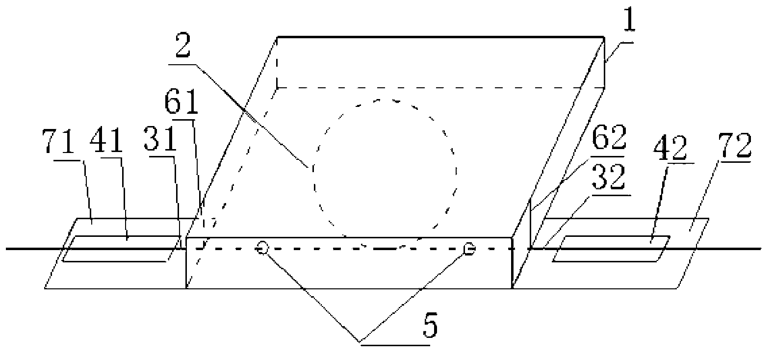
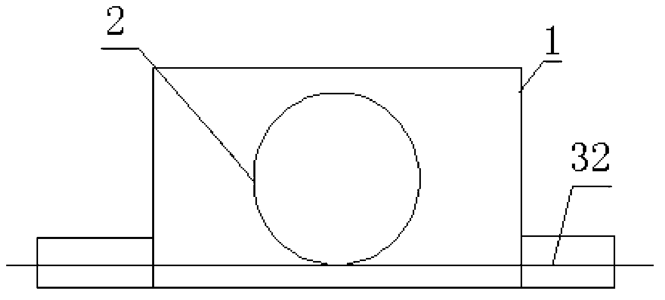
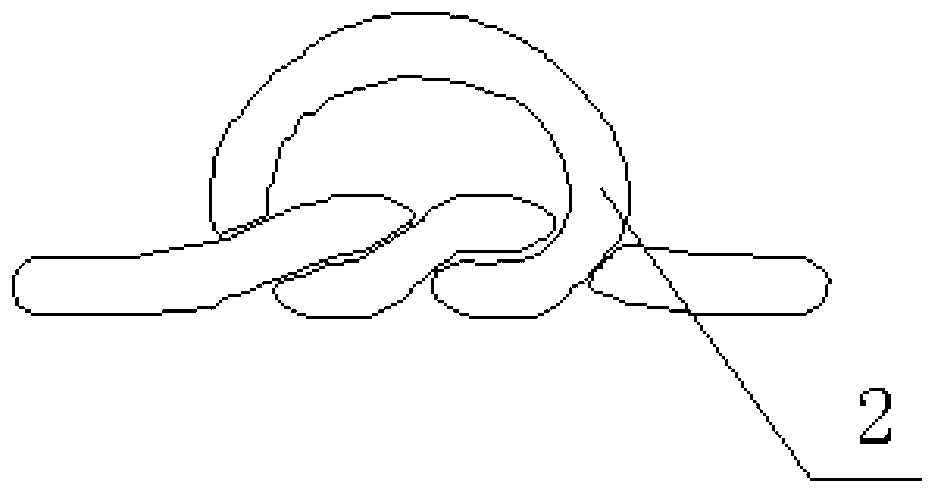
[0019] A crack monitoring sensor based on OTDR technology, such as figure 1 , 2 As shown, it includes a protective box, a bare fiber coil with two ends, and the first and second protected optical fibers. The bare fiber coil is arranged in the protective box, and the bare fiber coil is glued by epoxy resin Pasted in the protective box, the bottom two ends of the protective box are respectively provided with first and second outlets, the first and second outlets are used to lead out the first and second optical fibers with protective layers, and the second 1. The bottom of the protective box below the second outlet is respectively provided with the first and second optical fiber bonding platforms; since the bare optical fiber is easy to break, the bare optical fiber and the optical fiber with the protective layer are welded inside the protective box, and then the optical fiber with the protective layer is fused Lead out, not easy to break, that is, one end of the first protect...


PUM

PropertyMeasurementUnit
Diameteraaaaaaaaaa
Diameteraaaaaaaaaa

Abstract

The invention relates to a crack monitoring sensor and use method thereof based on an OTDR (optical time domain reflectometry) technique, and belongs to the technical field of monitoring of optical fibers. The crack monitoring sensor comprises a protection box, a bare optical fiber coil, a first optical fiber with a protecting layer, and a second optical fiber with a protecting layer, wherein the bare optical fiber coil is provided with two end joints, the bare optical fiber coil is an optical fiber coil which is formed by winding and knotting a bare optical fiber, and the diameter of the bare optical fiber coil is 14mm to 16mm. When the crack monitoring sensor is used, firstly, the outer optical fiber of the sensor is welded with the first optical fiber with the protecting layer and the second optical fiber with the protecting layer through the end joints, secondly, the adhering function of epoxy resin adhesive is released by an adhesive release agent, so that the inner optical of the sensor is ensured to be freely stretched along with the extension of the crack, and then the concrete is cast. The crack monitoring sensor and the use method have the advantages that the construction is convenient, the manufacturing is simple, the cost is low, the crack monitoring sensor and the use method are suitable for monitoring the cracks of various types of concrete inner structures, meanwhile, the operability is high, and the real-time monitoring and the distributed monitoring on the concrete inner structures are realized.

Description

technical field [0001] The invention relates to a crack monitoring sensor based on OTDR technology and a using method thereof, belonging to the technical field of optical fiber monitoring. Background technique [0002] Optical fiber monitoring of cracks in concrete structures is done by embedding optical fibers in concrete. When the concrete cracks, the optical fibers are bent, and when the bending radius is less than the critical radius of macro bending, Fresnel reflection and Rayleigh scattering will occur. Optical time domain reflectometer The optical loss at this time can be monitored. The fiber coil radius, that is, the macro-bending radius of the fiber, decreases continuously, and the reduced value has a certain relationship with the opening and closing degree of concrete cracks. At this time, the relationship between light loss and the opening of cracks inside and outside the concrete structure can be obtained, so as to judge the damage degree of the concrete structu...

Claims


Application Information

Patent Timeline
IPC IPC(8): G01B11/02G01N21/88
Inventor 崔少英包腾飞翟静宇蒋众喜刘月明崔少华李晓柱
Owner HOHAI UNIV
Why Eureka
Try Eureka