Mode add-drop multiplexing and demultiplexing device based on grating-assisting type coupler
A demultiplexer and coupler technology, which is applied in the field of mode multiplexing and demultiplexing, can solve the problem of difficult realization of more than three mode channels, increased device design complexity, and small device process tolerance. problem, to achieve the effect of easy integration and expansion, compact size, convenient and low-cost manufacturing
- Summary
- Abstract
- Description
- Claims
- Application Information
AI Technical Summary
Problems solved by technology
Method used
Image
Examples
Embodiment 1
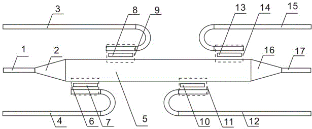
[0038] like figure 1 , Figure 5 and Image 6 As shown, the silicon-on-insulator (SOI) material with a top silicon thickness of 220 nm and a silicon oxide buried layer of 2 μm is used. The silicon strip waveguide with a width of 450 nm and a width of 1.1 um was fabricated by dry silicon etching, and the waveguide interval was 400 nm. A Bragg waveguide grating is etched in the center of the waveguide. The width of the rectangular grating teeth is 200 nm, and its period is 314 nm in the upper coupling region 6 and lower coupling region 11, and 347 nm in the upper coupling region 9 and lower coupling region 14. .
[0039] The grating period parameters in the above embodiments are designed for the device working in TE mode, and the device can also work in TM mode, only need to change different grating period parameters. The entire device only needs to be etched once to complete the fabrication.
Embodiment 2
[0041] like figure 1 , Figure 5 and Figure 7 As shown, the silicon-on-insulator (SOI) material with a top silicon thickness of 220 nm and a silicon oxide buried layer of 2 μm is used. The silicon ridge waveguide with a width of 450 nm and a width of 1.1 um was produced by twice silicon dry etching, with a ridge height of 160 nm and a waveguide interval of 400 nm. Bragg waveguide gratings are etched on the outer ridge in the center of the waveguide. The teeth of the rectangular grating are 200 nm, and its period is 308 nm in the upper coupling region 6 and the lower coupling region 11, and in the upper coupling region 9 and lower coupling region 14. 338 nm.
[0042] The grating period parameters in the above embodiments are designed for the device working in TE mode, and the device can also work in TM mode, only need to change different grating period parameters. The entire device only needs to be etched twice to complete the fabrication.
PUM
 Abstract
Description
Claims
Application Information
 - R&D
- Intellectual Property
- Life Sciences
- Materials
- Tech Scout
- Unparalleled Data Quality
- Higher Quality Content
- 60% Fewer Hallucinations
Browse by: Latest US Patents, China's latest patents, Technical Efficacy Thesaurus, Application Domain, Technology Topic, Popular Technical Reports.
© 2025 PatSnap. All rights reserved.Legal|Privacy policy|Modern Slavery Act Transparency Statement|Sitemap|About US| Contact US: help@patsnap.com


