Liquid tin target generator for laser plasma extreme ultraviolet light source

A technology of laser plasma and extreme ultraviolet light source, which is applied in the laser field, can solve the problems of low EUV conversion efficiency, general spectral characteristics of radiated light, and increase the difficulty of operation, so as to achieve high laser absorption efficiency and EUV conversion efficiency, and stable system Good sex, low impact effect

Inactive Publication Date: 2013-07-24
HUAZHONG UNIV OF SCI & TECH
View PDF6 Cites 5 Cited by
  • Summary
  • Abstract
  • Description
  • Claims
  • Application Information

AI Technical Summary

Problems solved by technology

[0007] In short, most of the existing mist liquid injection targets use liquefied rare gases such as xenon as targets, but generally the EUV conversion efficiency is not high, and the spectral characteristics of radiation light are average.
The droplet ejection target using tin and other targets with high conversion efficiency mostly adopts the pre-pulse technology, that is, before the main pulse arrives, a beam of lower energy laser is used to interact with the tin droplet to make it into a mist, so as to reduce the Small debris pollution, but it also increases the difficulty of operation and reduces the stability of the system

Method used


Image

  • Liquid tin target generator for laser plasma extreme ultraviolet light source
  • Liquid tin target generator for laser plasma extreme ultraviolet light source
  • Liquid tin target generator for laser plasma extreme ultraviolet light source

Examples


Embodiment Construction

[0020] The specific embodiments of the present invention will be further described below in conjunction with the accompanying drawings. It should be noted here that the descriptions of these embodiments are used to help understand the present invention, but are not intended to limit the present invention. In addition, the technical features involved in the various embodiments of the present invention described below can be combined with each other as long as they do not constitute a conflict with each other.

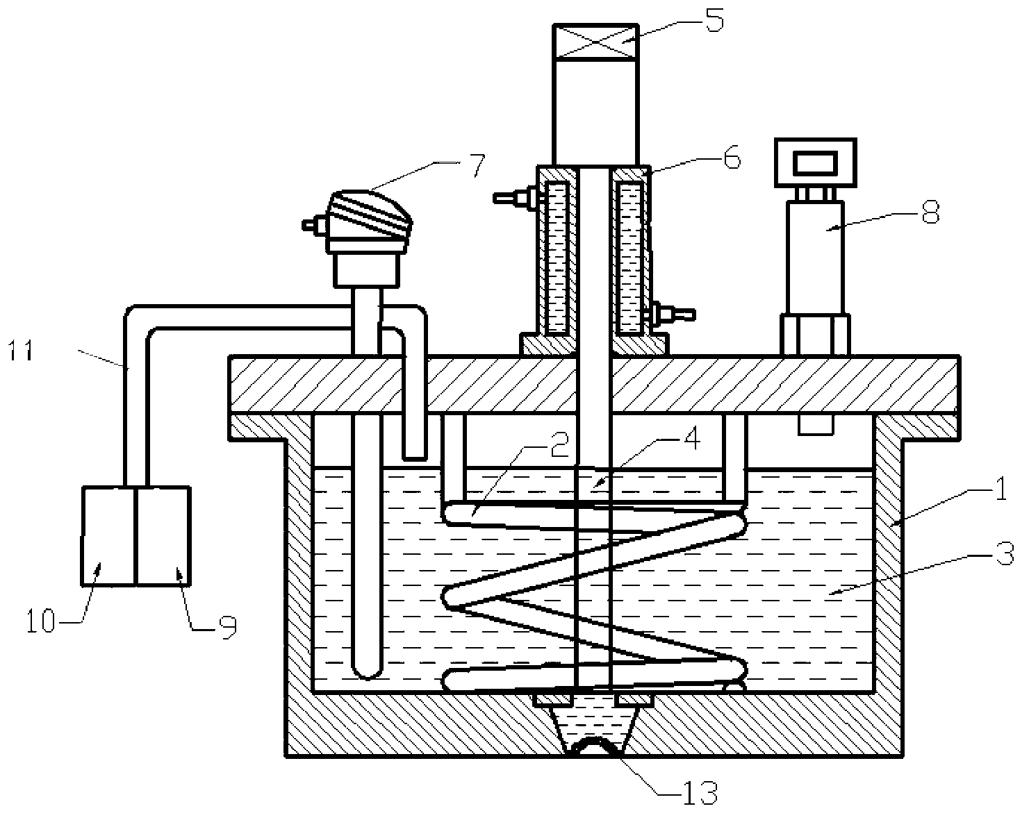
[0021] Such as figure 1 As shown, a liquid tin target generator for a laser plasma EUV light source provided by the example of the present invention includes a container 1 , an electric heater 2 , a vibrating rod 4 , a thermal resistor 7 , a pressure transmitter 8 and a nozzle 13 .

[0022] The test ends of the electric heater 2 and the thermal resistor 7 are all located in the container 1. When the tin material 3 is placed in the container 1, the test terminals of the ...


PUM

PropertyMeasurementUnit
depthaaaaaaaaaa
diameteraaaaaaaaaa

Abstract

The invention discloses a liquid tin target generator for a laser plasma extreme ultraviolet light source. The liquid tin target generator comprises a container, a vibrating rod, a nozzle, a heating system, a pressurizing system and a cooling mechanism, wherein micropores which are in central symmetry by using the center of the nozzle as a symmetric point and are uniformly distributed are formed in the nozzle, the diameter of the outlet end of each micropore is more than that of the inlet end of the micropore, and all micropores are pointed to a laser acting point from different angles. The heating system is used for melting a tin material which is in a solid state at a normal temperature into a molten tin material; the molten tin material is fragmented into liquid drops from a continuous liquid flow due to the vibration of the vibrating rod; the pressurizing system is used for applying a high pressure to the container to ensure that the molten tin material are sprayed out from the tiny micropores of the nozzle and form thick mist; a laser beam focuses on the converged liquid mist through a lens to generate EUV (Extreme Ultraviolet) radiation; and the vacuum system is used for vacuumizing a target chamber through a mechanical pump. The liquid tin generator has the advantages that the spraying distance of the target material is far, the influence on optical elements such as the nozzle and a converging lens is little, the laser absorption efficiency and the EUV conversion efficiency are high, and the system stability is good; and the liquid tin target generator is suitable for industrial large-scale production.

Description

technical field [0001] The invention belongs to the field of laser technology, and in particular relates to a liquid tin target generator for a laser plasma (LPP) extreme ultraviolet (EUV) light source, which is mainly used to generate a tin target generator with high EUV conversion efficiency, small debris pollution and stable system Liquid tin target. Background technique [0002] The chip industry has always had a theme: make transistors as small as possible, integrate as many transistors as possible, and continuously improve the integration of chips. The smallest scale that can be engraved by the chip process is mainly determined by the light wavelength of the light source used in the photolithography process. The shorter the wavelength of light used, the smaller the scale that can be achieved, and the higher the degree of integration that can be achieved. With the advancement of technology, the current state-of-the-art lithography technology cannot meet the requiremen...

Claims


Application Information

Patent Timeline
Patent Type & Authority Applications(China)
IPC IPC(8): G03F7/20H05G2/00
Inventor 孙茂元王新兵左都罗卢宏陆培祥
Owner HUAZHONG UNIV OF SCI & TECH
Why Eureka
Try Eureka