
Radiating method of aluminum electrolytic capacitor bunch of power unit of controller for electric vehicle

A technology for electric vehicle controllers and aluminum electrolytic capacitors, applied in electrolytic capacitors, capacitors, output power conversion devices, etc., can solve the problem of no heat dissipation channels, difficult assembly process of motor drive controllers, and reduced operating reliability of controllers, etc. question

Inactive Publication Date: 2013-07-24
周旺龙
View PDF0 Cites 6 Cited by
  • Summary
  • Abstract
  • Description
  • Claims
  • Application Information

AI Technical Summary

Problems solved by technology

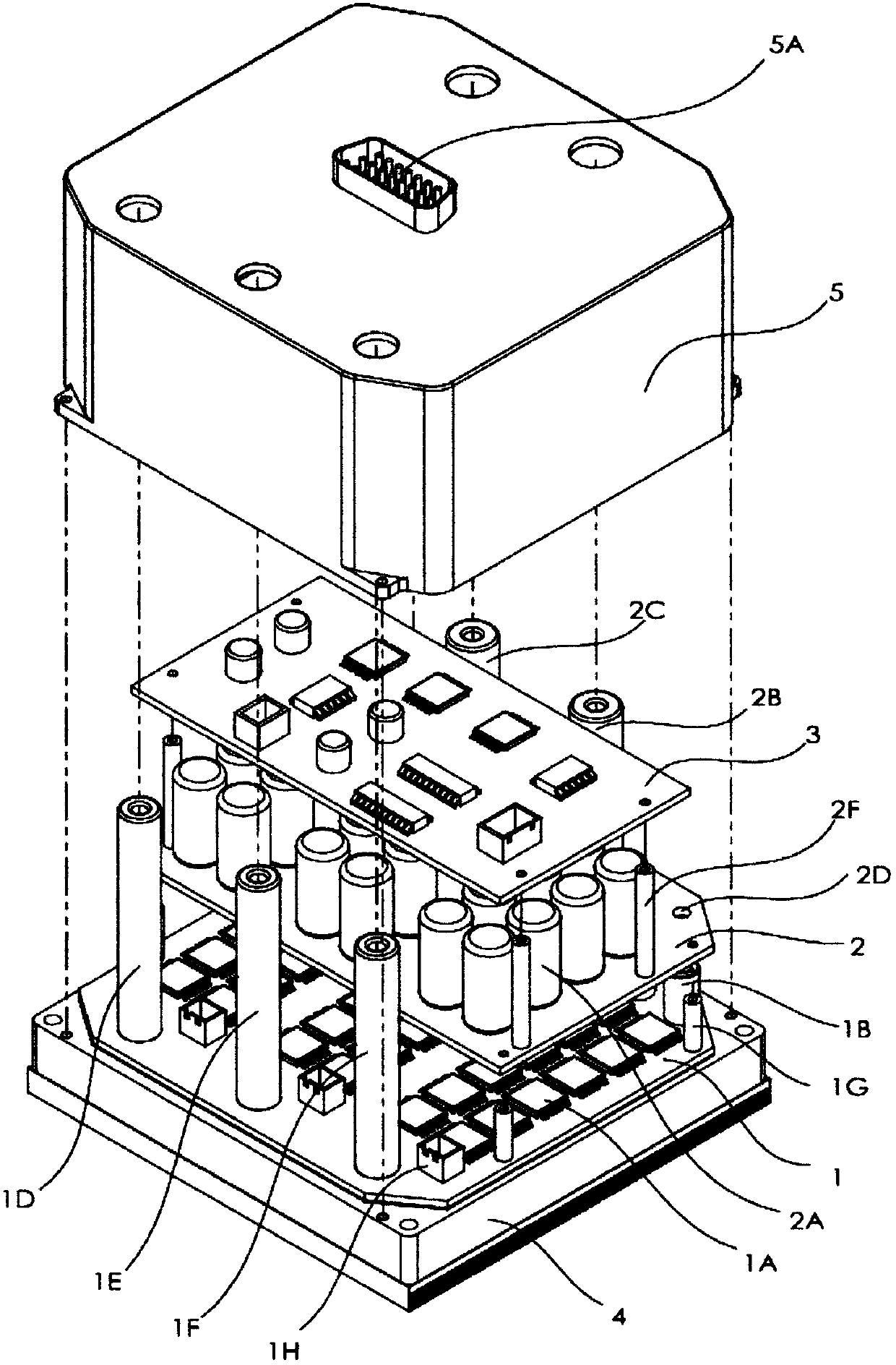
Since the power circuit is composed of many discrete components connected in parallel, the problem of voltage equalization and current sharing is more prominent; due to the complex structure, the existence of pulse current or ripple current in the main circuit makes the entire circuit structure space have strong electric and magnetic fields Radiation, which greatly interferes with the drive and control system of the motor controller, reduces the operating reliability of the controller; and because the ESR value of the aluminum electrolytic capacitor (2A) in the main circuit is large, a large amount of heat is generated during load operation, and Aluminum electrolytic capacitor 2A has no heat dissipation channel design, and can only conduct heat out through the conductor of the circuit itself, or dissipate heat into the air inside the drive controller housing, resulting in a high temperature rise in the controller housing, causing components or control The reliability of the controller itself is reduced; in addition, the current motor drive controller still has problems such as difficult assembly process and difficult miniaturization (see image 3 , Figure 4 )

Method used


Image

  • Radiating method of aluminum electrolytic capacitor bunch of power unit of controller for electric vehicle
  • Radiating method of aluminum electrolytic capacitor bunch of power unit of controller for electric vehicle
  • Radiating method of aluminum electrolytic capacitor bunch of power unit of controller for electric vehicle

Examples


Embodiment Construction

[0045] Preferred embodiments of the present invention will be described below with reference to the accompanying drawings.

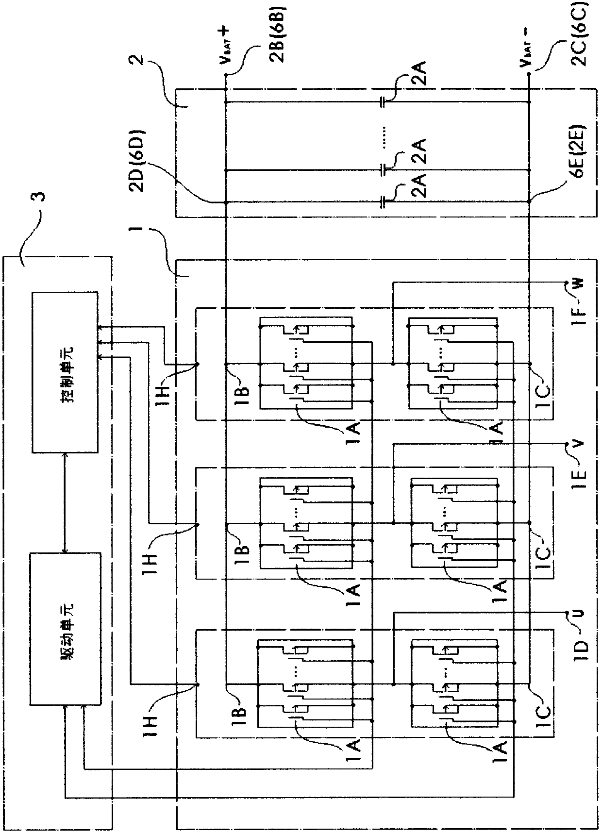
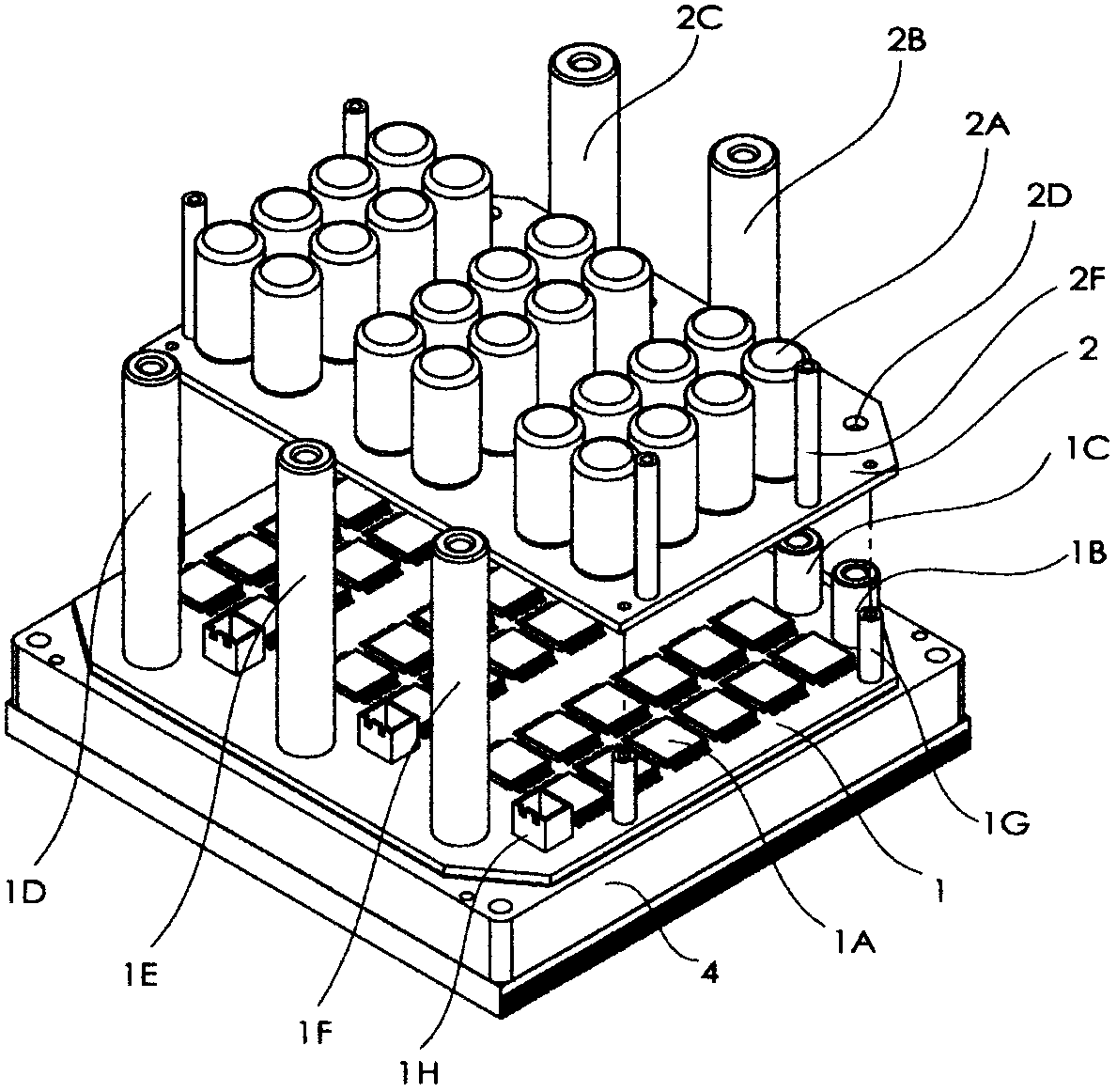
[0046] The aluminum electrolytic capacitors 2A are connected in parallel to form a capacitor module by using a conductive busbar structure, and are enclosed in a rectangular box-shaped casing to form a clustered aluminum electrolytic capacitor module block 6 . The upper part of the bundled square aluminum electrolytic capacitor module 6 has cylindrical terminals 6B and 6C for connecting wires with the battery; the bundled square aluminum electrolytic capacitor module 6 has three sets of positive lead-out terminals 6D and Negative lead-out terminal 6E is respectively connected and installed with three sets of positive input terminal 1B and negative input terminal 1C of power MOSFET module 1 mounted on power MOSFET (1A) aluminum substrate, and the box body 6 shell has a lower opening side plane as a heat dissipation surface 6A , fit with the radiator 4 at ...


PUM


Abstract

The invention discloses a radiating method of an aluminum electrolytic capacitor bunch of a power unit of a controller for an electric vehicle. The radiating method relates to aluminum electrolytic capacitor modules, a busbar terminal, a binding terminal pillar, a power switch device and a radiator of the power switch device, wherein the aluminum electrolytic capacitor modules are packed in an integrated outer shell in a bunching mode, the busbar terminal and the modules are integrally used for being connected with the power switch device, the binding terminal pillar, the power switch device and the radiator are used for being connected with a storage battery together with the modules in an integral mode, the integrated and square bunch aluminum electrolytic capacitor modules are provided with radiating surfaces which are installed with the radiator and a shell body of a controller in an attached mode, and heat produced by a capacitor is led out of the controller.

Description

Technical field: [0001] The invention relates to a low-voltage and low-power motor drive controller for a small electric vehicle, in particular to the layout, installation and heat dissipation structure of an aluminum electrolytic capacitor of the motor controller. Background technique: [0002] Programmable drive controllers for electric vehicles control the speed and torque of vehicle drive motors, and are one of the key components of electric vehicles. Different from ordinary motor drive controllers, electric vehicle motor drive controllers require a small Small size and high power, both have the characteristics of high power density. [0003] The drive controller can be roughly divided into three systems: power part, drive part and control part. The power unit mentioned in this description mainly refers to the power part of the controller. The power unit refers to the motor drive controller power circuit and heat dissipation system, including power switching devices; he...

Claims


Application Information

Patent Timeline
IPC IPC(8): H02M1/00H01G9/00H01G9/26H05K7/20
Inventor 周旺龙
Owner 周旺龙
Learn More