Supercharge Your Innovation With Domain-Expert AI Agents!

Hermetically-sealed chamber

A technology of sealing cavity and sealing groove, which is applied to the sealing of engines, pressure vessels, engine components, etc. It can solve the problems that the inside of the container cannot maintain vacuum, leakage, and sealing parts are difficult to seal, so as to reduce material costs and improve sealing The effect of stability and airtightness

Inactive Publication Date: 2013-07-24
IRIE KOKEN
View PDF4 Cites 0 Cited by
  • Summary
  • Abstract
  • Description
  • Claims
  • Application Information

AI Technical Summary

Problems solved by technology

[0005] However, in a vacuum container having such a joint structure, it is actually difficult to achieve sealing with the sealing member, causing large leakage, and sometimes the inside of the container cannot be kept vacuum.

Method used


Image

  • Hermetically-sealed chamber
  • Hermetically-sealed chamber
  • Hermetically-sealed chamber

Examples


Embodiment Construction

[0040] Hereinafter, embodiments of the present invention will be described with reference to the drawings.

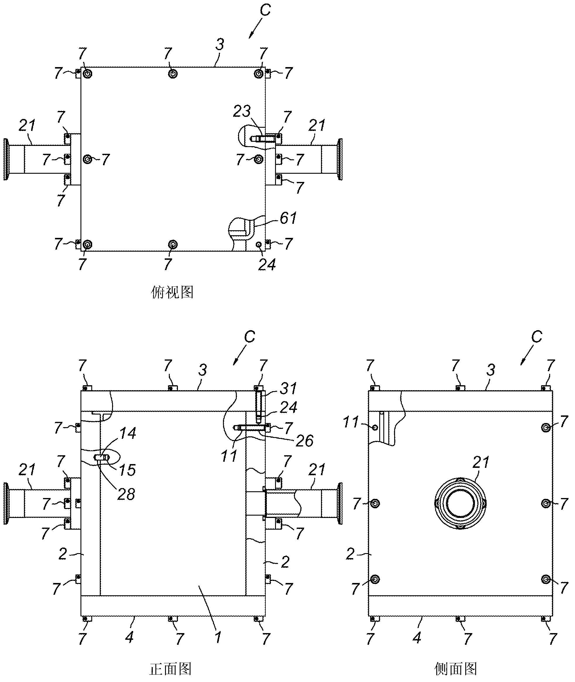
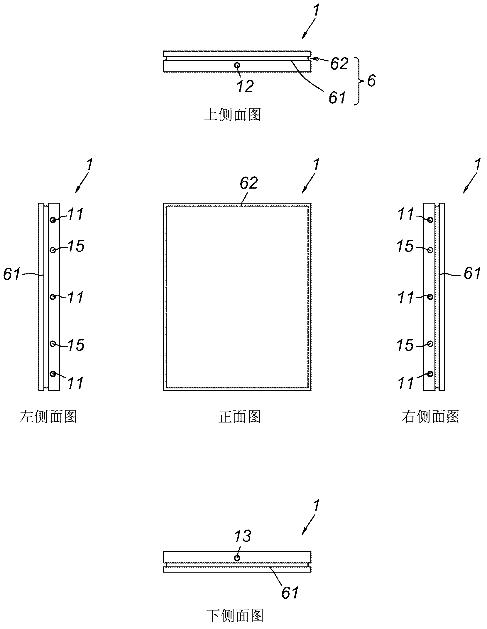
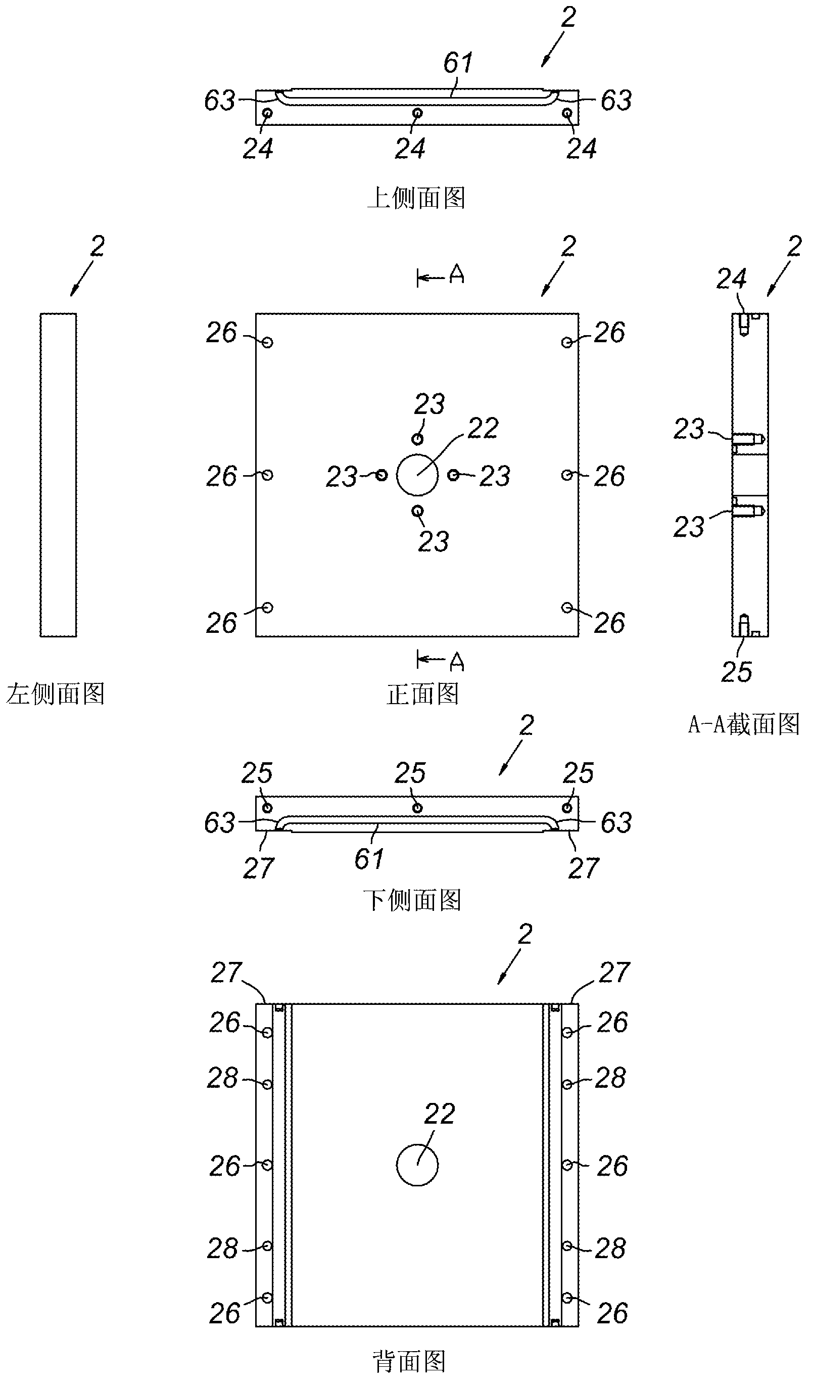
[0041] Such as figure 1 As shown, the sealed chamber C of the present invention is an assembled container that uses a plurality of plates 1, 2, 3, 4, sealing members 5, and bolts 7. For example, in a semiconductor manufacturing device, the inside is vacuumed. It can be used as a vacuum chamber for film formation and etching of semiconductor wafers.

[0042] In this embodiment, the sealed chamber C forms a planar quadrilateral formwork 8 by fixing two side plates 1, 1 facing each other and two side plates 2, 2 with exhaust ports by bolts 7, A top plate 3 is provided on the upper opening surface of the formwork 8, and a bottom plate 4 is provided on the lower opening surface, and then fixed with bolts 7 to form a rectangular parallelepiped hollow container with a sealed space inside. And, the joint surface between the formwork 8 and the top plate 3, the joint surface be...


PUM


Abstract

The aim of the present invention lies in embedding a gap formed at the corner of a sealing groove branch part formed at the joining surface of a sheet material in an assembled hermetically-sealed chamber in order to enhance the hermetic sealing. The present invention provides a hermetically-sealed chamber (C) which is assembled by joining sheet materials, wherein, when a sealant (5) is attached to a sealing groove (6) formed at the joining surface of an adjacent piece of sheet material, the branch part periphery of the sealant (5) (corner (53a)) is compressively deformed in the direction of a sealing groove corner (64a), whereby the corner (53a) of a sealing material branch part (53) is firmly pressed against the corner (64a) of a sealing groove branch part (64) and closely bonded thereto.

Description

technical field [0001] The present invention relates to an assembled sealed chamber that can be utilized in semiconductor manufacturing equipment, flat panel display manufacturing equipment, solar panel manufacturing equipment, and the like. Background technique [0002] Conventionally, a vacuum chamber or a gas-sealed chamber (hereinafter collectively referred to as a "sealed chamber") has been used when film formation or etching is performed on an object to be processed such as a semiconductor wafer or a liquid crystal display substrate. Such a sealed chamber is generally manufactured by using a relatively large module such as aluminum alloy or stainless steel, and cutting off the inside of the module by chip machining. Therefore, it is difficult to increase the size of the sealed chamber. In addition, there is a problem that the manufacturing cost becomes high due to reasons such as the need for large processing equipment and the waste of internal materials that have bee...

Claims


Application Information

Patent Timeline
Patent Type & Authority Applications(China)
IPC IPC(8): F16J15/10F16J12/00
CPCF16J15/021
Inventor 吉田秀彦中川雅晴矢部学齐藤宣和城户信二
Owner IRIE KOKEN
Features
  • R&D
  • Intellectual Property
  • Life Sciences
  • Materials
  • Tech Scout
  • Unparalleled Data Quality
  • Higher Quality Content
  • 60% Fewer Hallucinations
Learn More