
Heat ray shielding material

A technology of heat ray shielding and particles, which is applied in thin material processing, other chemical processes, instruments, etc., can solve the problems of reduced heat ray shielding effect, insufficient light resistance of diimonium-based materials, insufficient visible light transmittance, etc. , to achieve the effect of excellent radio wave permeability and light resistance, and high shielding rate

Inactive Publication Date: 2013-07-24
FUJIFILM CORP
View PDF10 Cites 8 Cited by
  • Summary
  • Abstract
  • Description
  • Claims
  • Application Information

AI Technical Summary

Problems solved by technology

However, its visible light transmittance is 60%, which has the problem of insufficient visible light transmittance.
In addition, the light resistance of diimonium-based substances is not sufficient, and even if an ultraviolet absorbing substance is contained in the same layer, it will deteriorate due to heat generation of the film itself based on heat ray absorption, ultraviolet rays contained in sunlight, etc., and has heat rays. The problem of rapid reduction of shielding effect

Method used


Image

  • Heat ray shielding material
  • Heat ray shielding material
  • Heat ray shielding material

Examples


manufacture example 1

[0148] -Synthesis of flat silver particles-

[0149] --Synthesis process of flat core particles--

[0150] To 50 mL of a 2.5 mmol / L sodium citrate aqueous solution was added 2.5 mL of a 0.5 g / L polystyrenesulfonic acid aqueous solution, followed by heating to 35°C. To this solution was added 3 mL of a 10 mmol / L sodium borohydride aqueous solution, and 50 mL of a 0.5 mmol / L silver nitrate aqueous solution was added while stirring at 20 mL / min. This solution was stirred for 30 minutes to prepare a seed solution (seed solution).

[0151] --The first growth process of flat particles--

[0152] Subsequently, 87.1 mL of ion-exchanged water was added to 132.7 mL of a 2.5 mmol / L sodium citrate aqueous solution, and the mixture was heated to 35°C. To this solution were added 2 mL of a 10 mmol / L ascorbic acid aqueous solution, 42.4 mL of the above seed solution, and 79.6 mL of a 0.5 mmol / L silver nitrate aqueous solution while stirring at 10 mL / min.

[0153] --The second growth proces...

manufacture example 2

[0172] In manufacture example 1, except having added 72 mL of ion-exchange water instead of adding 0.83 mol / L NaOH aqueous solution 72mL, it carried out similarly to manufacture example 1, and produced the flat silver particle dispersion liquid b.

manufacture example 3

[0174] In Production Example 1, 87.1 mL of ion-exchanged water was not added, the amount of the seed solution added was changed to 127.6 mL, and 72 mL of 0.83 mol / L NaOH aqueous solution was added instead of 72 mL of 0.08 mol / L NaOH aqueous solution. Otherwise, silver tabular particle dispersion liquid c was produced in the same manner as in Production Example 1.


PUM

PropertyMeasurementUnit
particle sizeaaaaaaaaaa
hazeaaaaaaaaaa

Abstract

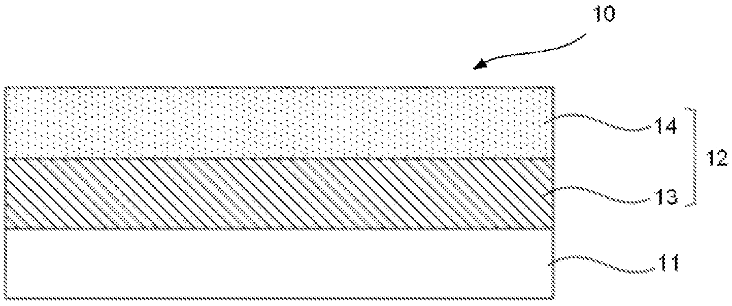
Provided is a heat ray shielding material that has superior visible light transmittance, radio wave transmittance, and light resistance, can shield infrared rays across a wide band, and has a high infrared ray shielding rate. The heat ray shielding material has a heat ray shielding layer that contains silver plate particles and metal oxide particles. Preferable are: an embodiment wherein the metal oxide particles are tin-doped indium oxide particles; an embodiment wherein the silver plate particles and the metal oxide particles are mixed and dispersed in a binder in the heat ray shielding layer; and an embodiment wherein a silver-plate-particle-containing layer that contains the silver plate particles and a metal-oxide-containing layer that contains the metal oxide are laminated in the heat ray shielding layer.

Description

technical field [0001] The present invention relates to a heat ray shielding material having excellent visible light transmittance, radio wave transmittance and light resistance, capable of shielding near-infrared rays over a wide frequency band, and having a high shielding rate of near-infrared rays. Background technique [0002] In recent years, as one of energy-saving measures for reducing carbon dioxide, materials capable of imparting heat ray shielding properties to automobile windows and building windows have been developed. For example, metal Ag thin films are generally used as heat ray reflective materials because of their high reflectivity, but they have problems of low visible light transmittance and radio wave transmittance because they reflect not only visible light and heat rays but also radio waves. In order to improve the transmittance of visible light, Low-E glass (manufactured by Asahi Glass Co., Ltd., for example) using Ag and ZnO multilayer films is used i...

Claims


Application Information

Patent Timeline
Patent Type & Authority Applications(China)
IPC IPC(8): G02B5/22C03C17/34C03C27/12C09K3/00G02B5/26
CPCC03C17/34C03C2217/465G02B5/208C03C2217/479C03C2217/476G02B5/206C03C17/007Y10T428/256
Inventor 镰田晃清都尚治
Owner FUJIFILM CORP
Learn More