Fully-automatic quantitative and energy-saving material dispatching system

A scheduling system, fully automatic technology, applied in waste fuel, specific purpose bioreactor/fermenter, biomass post-processing, etc., can solve the problem of reducing the production efficiency of the process system, increasing the fixed cost of the process system, and consuming external energy of the system and other issues to achieve the effect of reducing fixed investment, reducing complexity, and improving environmental conditions

Active Publication Date: 2013-08-07
SHANGHAI JIAO TONG UNIV
View PDF8 Cites 2 Cited by
  • Summary
  • Abstract
  • Description
  • Claims
  • Application Information

AI Technical Summary

Problems solved by technology

However, the use of pumps and gas delivery machinery will inevitably increase the fixed cost of the entire process system, and the external energy of the system needs to be consumed during the work process
In addition, it will also have adverse effects on various microbial activities in the suspension, thereby reducing the production efficiency of the process system

Method used


Image

  • Fully-automatic quantitative and energy-saving material dispatching system
  • Fully-automatic quantitative and energy-saving material dispatching system

Examples


Embodiment 1

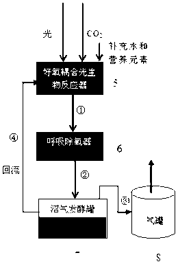
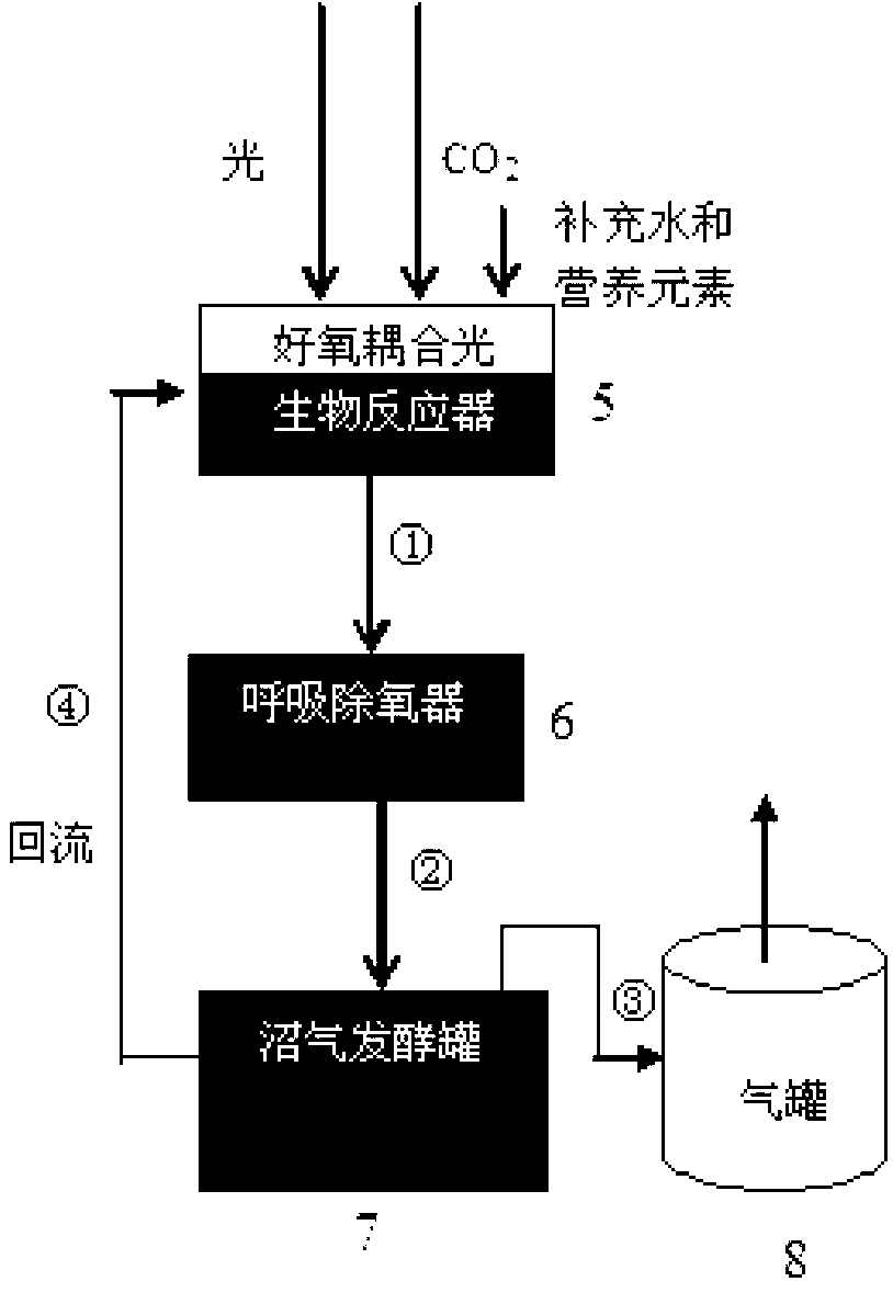
[0028] Such as Figure 1~2 As shown, the fully automatic quantitative and energy-saving material dispatching system includes a good-yang coupling photobioreactor 5, a respiratory deaerator 6, and a biogas fermentation tank 7 arranged up and down in sequence. The good-yang coupling photobioreactor 5 passes through the tube The road a1 is connected to the respiratory deaerator 6, and the respiratory deaerator 6 is connected to the biogas fermentation tank 7 through the pipeline b2, and the biogas fermentation tank 7 is connected to the gas storage tank 8 through the pipeline c3, and connected to the coupling photobiology through the return pipeline d4 Reactor 5; the pipeline a1, pipeline b2, pipeline c3, and return pipeline d4 are all connected to the liquid level control mechanism;

[0029] Wherein, the aerobic coupled photobioreactor 5 is established by coupling a photobioreactor with an aerobic bioreactor. The eutrophic coupled photobioreactor contains water, nutrients and a...

Embodiment 2

[0039] Such as figure 1 As shown, the equipment used in this embodiment includes an independently set aerobic coupled photobioreactor, a respiratory deaerator, an anaerobic fermentation tank and a liquid level control mechanism.

[0040] The above-mentioned equipment is used to realize the automatic quantitative energy-saving material scheduling problem of the technical process in the patent 201310151302.4, and specifically includes the following steps (such as figure 1 shown):

[0041] Step 1: Open pipeline a1, pipeline b2 and pipeline c3, and close return pipeline d4. The suspension of microalgae and aerobic bacteria in the aerobic coupling photobioreactor with an effective volume of 60000L enters the breathing deaerator with a volume of 30000L through the pipeline a1 under the action of its own gravity, and at the same time the Under the action of its own gravity, the suspension also enters the biogas fermentation tank with an effective volume of 90000L through the pipeli...

Embodiment 3

[0047] Such as figure 1 As shown, the equipment used in this embodiment includes an independently set aerobic coupled photobioreactor, a respiratory deaerator, an anaerobic fermentation tank and a liquid level control mechanism.

[0048] The above-mentioned equipment is used to realize the automatic quantitative energy-saving material scheduling problem of the technical process in the patent 201310151302.4, and specifically includes the following steps (such as figure 1 shown):

[0049] Step 1: Open pipeline a1, pipeline b2 and pipeline c3, and close return pipeline d4. The suspension of microalgae and aerobic bacteria in the aerobic coupled photobioreactor with an effective volume of 5000L enters the respiratory deaerator with a volume of 4500L through the pipeline a1 under the action of its own gravity, and at the same time the Under the action of its own gravity, the suspension also enters the biogas fermentation tank with an effective volume of 8000L through the pipeline...


PUM


Abstract

The invention relates to a fully-automatic quantitative and energy-saving material dispatching system comprising an aerobic coupling photobioreactor, a breathing deaerator and a methane fermentation tank which are sequentially and vertically arranged, wherein the aerobic coupling photobioreactor is connected with the breathing deaerator through a pipeline a; the breathing deaerator is connected with the methane fermentation tank through a pipeline b; the methane fermentation tank is connected with an air storage tank through a pipeline c and connected with the aerobic coupling photobioreactor through a return pipeline d; and the pipeline a, the pipeline b, the pipeline c and the return pipeline d are all connected with a liquid level control mechanism. Compared with the prior art, the fully-automatic quantitative and energy-saving material dispatching system has the advantages that the fully-automatic operation of the integral system and the quantitative conveyance of all materials can be driven only by means of the methane pressure energy inside the system through coupling methane pressure, fluid gravity and liquid level control, almost no energy from the outside of the system is needed, and meanwhile, no manual intervention is needed.

Description

technical field [0001] The invention relates to the field of new energy, in particular to a fully automatic quantitative and energy-saving material scheduling system. Background technique [0002] Over the past few decades, fossil fuels have played an important role in promoting the world economy and industrialization process. However, supply shortages and rising prices have begun to make them a counter force that restricts development. At the same time, the use of a large amount of fossil fuels has created serious environmental problems, among which CO in the atmosphere 2 The dramatic rise in concentrations has led to climate change that threatens human existence. In this context, finding and developing renewable energy has become an important strategy for countries all over the world. [0003] Patent application 201310151302.4 discloses a new biochemical process for realizing solar energy utilization. The method includes the following steps: (1) In the photobioreactor, t...

Claims


Application Information

Patent Timeline
Patent Type & Authority Applications(China)
IPC IPC(8): C12M1/36C12M1/107
CPCC12M21/04C12M21/02C12M23/58C12M29/20Y02E50/30
Inventor 靳强
Owner SHANGHAI JIAO TONG UNIV
Why Eureka
Try Eureka