Method and device for strengthening underwater laser micro shot blasting of fastener hole

A shot peening and underwater laser technology is applied to the device for realizing this method, the underwater laser micro shot peening of fastening holes, and the strengthening of the inner wall of fastening holes, which can solve the problem of reduced shock wave energy and large alternating current. The load is harsh in the working environment, and the compressive stress layer cannot be generated to achieve the effect of ensuring balance.

Inactive Publication Date: 2013-08-07
JIANGSU UNIV
View PDF4 Cites 14 Cited by
  • Summary
  • Abstract
  • Description
  • Claims
  • Application Information

AI Technical Summary

Problems solved by technology

[0005] However, when the hole wall is strengthened by reflecting the shock wave, part of the shock wave energy will be absorbed by the reflection cone, so the shock wave energy acting on

Method used


Image

  • Method and device for strengthening underwater laser micro shot blasting of fastener hole

Examples


Embodiment 1

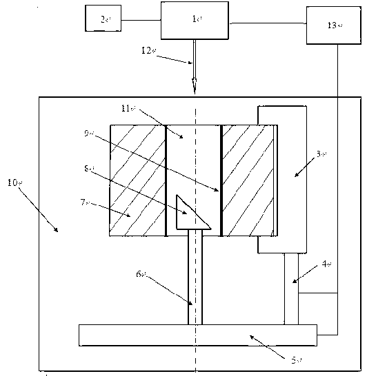
[0030] A fastening hole laser micro shot peening strengthening device, such as figure 1 As shown, it includes: a laser 1, a laser control device 2, a water tank 10, a five-axis worktable 5, a fixture I3, a fixture II6, a feeding device 4, a total mirror 8 and a numerical control system 13.

[0031] Fixture II6 is installed on the five-axis table 5; fixture I3 is connected to the five-axis table 5 through the feed device 4; the total mirror 7 is installed on the fixture II6; the laser 1 is located opposite to the five-axis table 5; the water tank 10 is located on the Below the five-axis table 5 ; the numerical control system 13 controls the output pulse of the laser 1 , the feed cycle of the feeding device 4 and the movement of the five-axis table 5 .

Embodiment 2

[0033] The specific steps of implementing a method for underwater laser micro shot peening of fastening holes are:

[0034] (1) Place the five-axis workbench 5 in the water tank 10;

[0035] (2) Install the workpiece 7 on the fixture Ⅰ3, and coat the inner wall of the fastening hole 11 with an absorbing layer (black paint) 9, and then install the total reflection mirror 8 on the fixture Ⅱ6 to ensure that the angle between the total reflection mirror 8 and the horizontal plane is 45°;

[0036] (3) Set the pulse energy of laser 1 to 0.5 J, the spot diameter D to 0.2 mm and the pulse width to 10 ns through the laser control device 2;

[0037] (4) Adjust the five-axis worktable 5 by the numerical control system 13 so that the incident laser beam 12 is coaxial with the fastening hole 11 and the focus of the laser beam 12 is positioned on the total reflection mirror 8;

[0038] (5) Adjust the feeding device 4 through the numerical control system 13, so that the laser beam reflecte...

Embodiment 3

[0042] The parameters of the high-power pulsed laser 1 in Example 2 were changed to a pulse energy of 1 J, a spot diameter of 0.5 mm and a pulse width of 20 ns, and other methods and steps remained unchanged.


PUM

PropertyMeasurementUnit
Spot diameteraaaaaaaaaa
Pulse widthaaaaaaaaaa
Diameteraaaaaaaaaa

Abstract

The invention discloses a method and a device for strengthening underwater laser micro shot blasting of a fastener hole. The fastener hole is placed in water, small light spots are irradiated on an absorption layer of the inner wall of the fastener hole through a laser beam of the small light spots with high power reflected by a full reflecting mirror and arranged inside the fastener hole, and the energy of an impact wave finally generated directly acts on the wall of the hole, so that a high-temperature and high-pressure plasma is generated, and a high-pressure impact wave is generated after the explosion of the plasma for strengthening the inner wall of the fastener hole. The device for using the method comprises a laser, a laser control device, a water tank, a five-shaft working table, a clamping apparatus I, a clamping apparatus II, a feeding device, a total reflecting mirror and a digital control system which are connected in sequence. The method and the device can form deep high-amplitude residual compressive stress layer so as to be suitable for bad working environment with large alternating load, and can be applied for strengthening underwater laser micro shot blasting of the fastener hole.

Description

technical field [0001] The invention relates to the field of laser processing, in particular to a method for underwater laser micro-shot peening of fastening holes and a device for realizing the method, especially suitable for strengthening the inner wall of fastening holes with large alternating loads and harsh working environments . Background technique [0002] Fastening holes are common parts of local stress concentration in mechanical equipment, which are prone to fatigue cracks under alternating loads, which will greatly reduce the safety, reliability and service life of equipment, and increase maintenance costs. Stress concentration at the edge of the fastening hole and a large number of potential cracks are the main causes of component fatigue damage. Therefore, the key to improving the fatigue performance of components is to strengthen the inner wall of the fastening hole to improve its fatigue resistance. The balance of hole wall strengthening is an important pro...

Claims


Application Information

Patent Timeline
IPC IPC(8): C21D7/06
Inventor 罗开玉罗密鲁金忠林通
Owner JIANGSU UNIV
Why Eureka
Try Eureka