Supercharge Your Innovation With Domain-Expert AI Agents!

Ultrasonic wave detection system and method capable of improving ultrasonic wave detection precision

A detection system and ultrasonic technology, which is applied to the analysis of solids using sonic/ultrasonic/infrasonic waves, etc., can solve the problems of weak echo signals, the inability of ultrasonic probes to effectively identify and record, and changes in the angle of ultrasonic probes when the detection vehicle travels.

Inactive Publication Date: 2013-08-07
BEIJING INFORMATION SCI & TECH UNIV
View PDF5 Cites 1 Cited by
  • Summary
  • Abstract
  • Description
  • Claims
  • Application Information

AI Technical Summary

Problems solved by technology

At present, it is common to use vehicle-mounted ultrasonic detection systems, but the detection accuracy is not ideal. The main reason is that the angle of the ultrasonic probe changes due to the unsteady movement of the detection vehicle. The propagation paths of the transmitted signal and the echo signal do not coincide, so that the ultrasonic probe can only receive a weak echo signal and cannot effectively identify and record
Furthermore, the sediment inside the drainage pipe, such as silt and plastic, has a certain absorbing effect, which will cause the echo signal to be weaker.
The detection accuracy of the ultrasonic detection system is very unsatisfactory when working in the above situations

Method used


Image

  • Ultrasonic wave detection system and method capable of improving ultrasonic wave detection precision
  • Ultrasonic wave detection system and method capable of improving ultrasonic wave detection precision
  • Ultrasonic wave detection system and method capable of improving ultrasonic wave detection precision

Examples


Embodiment Construction

[0020] The present invention will be described in detail below in conjunction with the accompanying drawings and embodiments.

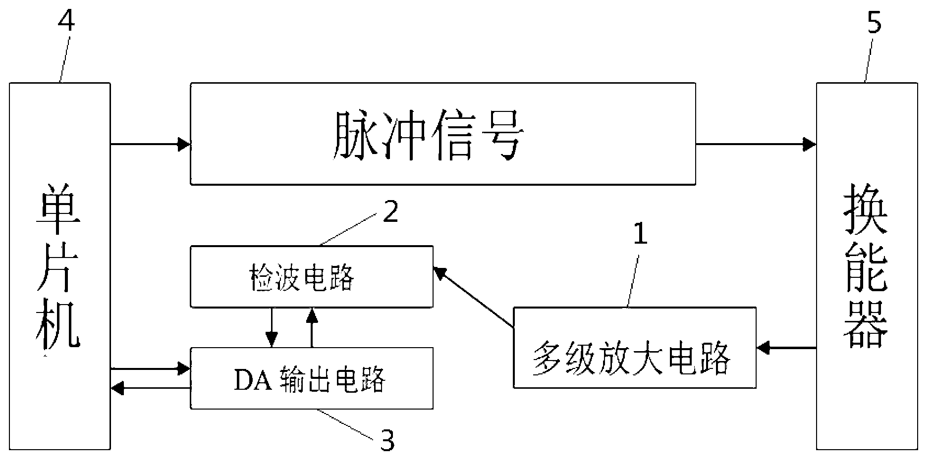
[0021] Such as figure 1 As shown, the ultrasonic detection system of the present invention includes a multi-stage amplifier circuit 1 , a detection circuit 2 , a DA output circuit 3 , a single-chip microcomputer 4 and a transducer 5 .

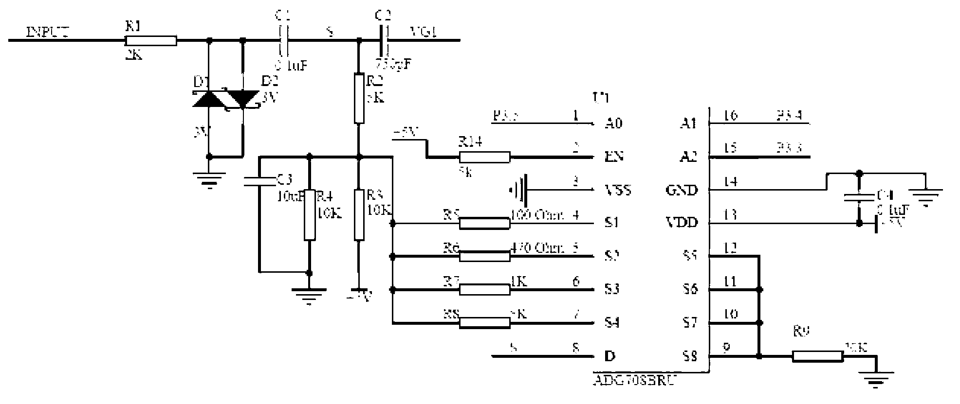
[0022] Such as figure 2As shown, the multi-stage amplifying circuit 1 includes an echo signal path, a voltage dividing amplifying circuit and a multiplexer. The echo signal path includes 2K resistor R1, 3V regulator tubes D1 and D2, 0.1 microfarad capacitor C1, and 750 picofarad capacitor C2, in which resistor R1, capacitor C1 and capacitor C2 are connected in series in sequence, and the function of capacitor C1 and C2 is to preserve The ultrasonic echo signal of the target frequency is used to filter out the clutter signal; the positive and negative voltage regulator tubes D1 and D2 are reversed and connected in pa...


PUM


Abstract

The invention relates to an ultrasonic wave detection system and an ultrasonic wave detection method capable of improving ultrasonic wave detection precision. The ultrasonic wave detection system is characterized by comprising a multiple-stage amplifier, a wave detection circuit, a DA (Digital to Analog) output circuit, a micro controller and an energy converter, wherein the micro controller emits pulse signals in certain frequencies to drive the energy converter to emit ultrasonic waves; after the ultrasonic waves are reflected by a barrier, echo signals of the ultrasonic waves are received by the input end of the multiple-stage amplifier, are input into the wave detection circuit after being amplified by the multiple-stage amplifier and flow to the detection end of the micro controller after being filtered and maintained by the wave detection circuit; and the DA output circuit drives the comparison end of the micro controller to generate a reference voltage, and the micro controller compares the voltages of the echo signals of the ultrasonic waves with the reference voltage and terminates timing when voltage values of the echo signals of the ultrasonic waves are higher than or equal to the reference voltage. According to the ultrasonic wave detection system and the ultrasonic wave detection method, the detection precision of the ultrasonic wave detection system under various complex environments of drainage pipelines and a condition that the inner walls of the pipelines are uneven can be remarkably improved.

Description

technical field [0001] The invention relates to an ultrasonic detection system and method, in particular to an ultrasonic detection system and method that can significantly improve the accuracy of ultrasonic detection when the measured environment is a closed environment such as a drainage pipe. Background technique [0002] Due to the rapid development of the city, some of the infrastructure supporting the city cannot keep up with the speed of urban development. Including not only the insufficient number of manhole covers on urban roads, but also the high hardening index of urban roads. Because the rainwater falls into the natural soil, it will slowly collect into the groundwater, and then enter the urban river, but if it is a hardened road surface (asphalt road, cement road), the rainwater will not be able to penetrate into the groundwater through the ground, and can only enter the drainage pipes. If it is not removed in time, it will cause a large amount of water accumul...

Claims


Application Information

Patent Timeline
IPC IPC(8): G01N29/07
Inventor 黄民王小川李天剑高宏孙清源付文悦林向真
Owner BEIJING INFORMATION SCI & TECH UNIV
Features
  • R&D
  • Intellectual Property
  • Life Sciences
  • Materials
  • Tech Scout
  • Unparalleled Data Quality
  • Higher Quality Content
  • 60% Fewer Hallucinations
Learn More