Periodic permanent magnetic structure

A technology of periodic permanent magnets and permanent magnets, applied in discharge tubes, electrical components, circuits, etc., can solve the problems of the structure description of the magnetic focusing system, the increase of the volume of the permanent magnet focusing system, and the disadvantage of miniaturization of the traveling wave tube, and achieve strong performance. Practical value, favorable for miniaturization, and excellent performance

Active Publication Date: 2013-08-07
SOUTHWEST INST OF APPLIED MAGNETICS
View PDF4 Cites 2 Cited by
  • Summary
  • Abstract
  • Description
  • Claims
  • Application Information

AI Technical Summary

Problems solved by technology

The disadvantage of uniform field permanent magnet focusing is: in order to obtain a good pass rate for the electron beam, the length of the slow wave system is usually designed to be roughly equal to the inner diameter of the permanent magnet focusing

Method used


Image

  • Periodic permanent magnetic structure
  • Periodic permanent magnetic structure
  • Periodic permanent magnetic structure

Examples


Example Embodiment

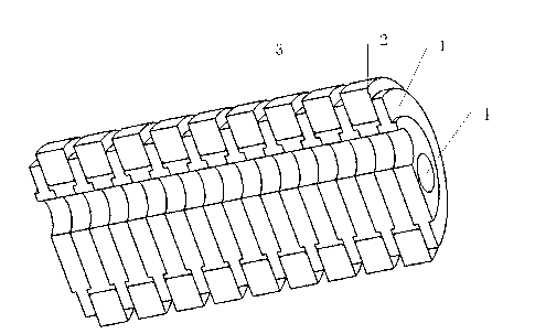
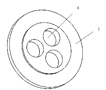
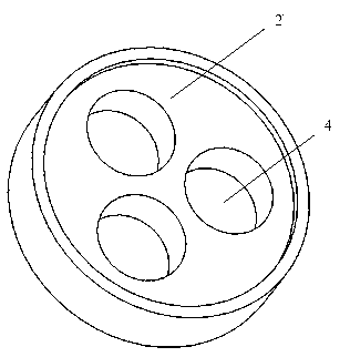
[0044] Example 1: figure 1 It is a periodic permanent magnet structure of three electron beam channels. figure 2 It is the structure of pole shoe (1). image 3 It is the structure of the positioning ring (2). The diameter of the electron beam channel in this embodiment is 2.2mm, the period of the periodic permanent magnet structure is 5.6mm, the peak value of the axial magnetic flux density of the electron beam channel is 218mT, and the ratio of the peak value of the radial magnetic flux density to the peak value of the axial magnetic flux density Is 0.52%. Figure 4 Is the magnetic flux density distribution diagram of the electron beam channel in this example on the central axis. Figure 4 in, B R Is the radial magnetic flux density, B Z / 100 is one hundredth of the axial magnetic flux density.

Example Embodiment

[0045] Example 2: Figure 5 It is a periodic permanent magnet structure of four electron beam channels. The diameter of the electron beam channel in this embodiment is 2.2mm, the period of the periodic permanent magnet structure is 5.6mm, the axial peak magnetic flux density of the electron beam channel is 218mT, and the radial magnetic The ratio of the peak flux density to the peak axial magnetic flux density is 1.02%. Image 6 Is the magnetic flux density distribution diagram on the central axis of the electron beam channel in this example. Image 6 in, B R Is the radial magnetic flux density, B Z / 100 is one hundredth of the axial magnetic flux density.

Example Embodiment

[0046] Example 3: Figure 7 It is a periodic permanent magnet structure with five electron beam channels. The diameter of the electron beam channel in this embodiment is 2.2 mm, the period of the periodic permanent magnet structure is 5.6 mm, the peak value of the axial magnetic flux density of the electron beam channel is 220 mT, and the radial magnetic flux The ratio of peak density to peak axial magnetic flux density is 1.78%; Figure 8 Is the magnetic flux density distribution diagram on the central axis of the electron beam channel in this example. Figure 8 in, B R Is the radial magnetic flux density, B Z / 100 is one hundredth of the axial magnetic flux density.


PUM

PropertyMeasurementUnit
Diameteraaaaaaaaaa

Abstract

The invention discloses a periodic permanent magnetic structure and belongs to the field of microwave vacuum electronic devices. The periodic permanent magnetic structure comprises pole shoes (1), positioning rings (2), permanent magnetic rings (3), and electronic injection channels (4). The pole shoes (1), the positioning rings (2) and the permanent magnetic rings (3) are periodically arranged to form the periodic permanent magnetic structure. The periodic permanent magnetic structure has the advantages that with the purpose of miniaturization of spiral line traveling-wave tubes, the ratio of a radial magnetic flux density peak valve BR0 and a axial magnetic flux density peak value BZo can be optimized to be 1 %. The periodic permanent magnetic structure is fine in performance, is favorable for miniaturization of the microwave vacuum electronic devices, and has a high practical value.

Description

technical field [0001] The invention belongs to the field of microwave vacuum electronic devices, and specifically relates to a periodic permanent magnet structure for a helical traveling wave tube, which is usually called a periodic permanent magnet focusing system, or a permanent magnet assembly of a traveling wave tube. Background technique [0002] Microwave vacuum electronic devices are an important class of electronic devices in national defense equipment, and are the heart of radar, communication, electronic countermeasures, telemetry and remote control and precision guidance equipment. It uses electrons to interact with an electromagnetic field in a vacuum, converting the direct current energy of the electrons into another form of microwave energy. As a microwave vacuum power amplifier, traveling wave tubes have the advantages of wide frequency band, large gain, high efficiency, and large output power, and are widely used in various military microwave transmitters. ...

Claims


Application Information

Patent Timeline
IPC IPC(8): H01J23/087
Inventor 王林梅张明王敬东李汴王磊袁涛邹杨徐亮
Owner SOUTHWEST INST OF APPLIED MAGNETICS
Why Eureka
Try Eureka