Triggering device and triggering control method for thyristor valve block of high-voltage TSC (thyristor switched capacitor)

A trigger device and thyristor valve technology, which is applied in the direction of electrical components, electronic switches, flexible AC transmission systems, etc., can solve the problems of complex trigger control methods and complex trigger device structures, and achieve simple trigger control methods, fast switching, The effect of reducing complexity

Active Publication Date: 2013-08-07
黑龙江特通电气股份有限公司
View PDF6 Cites 7 Cited by
  • Summary
  • Abstract
  • Description
  • Claims
  • Application Information

AI Technical Summary

Problems solved by technology

[0004] The present invention proposes a trigger device and a trigger control method for a thyristor valve group of a high-voltage TSC in order to solve the problems of the existing trigger device with complicated structure and trigger control method

Method used


Image

  • Triggering device and triggering control method for thyristor valve block of high-voltage TSC (thyristor switched capacitor)
  • Triggering device and triggering control method for thyristor valve block of high-voltage TSC (thyristor switched capacitor)
  • Triggering device and triggering control method for thyristor valve block of high-voltage TSC (thyristor switched capacitor)

Examples


specific Embodiment approach 1

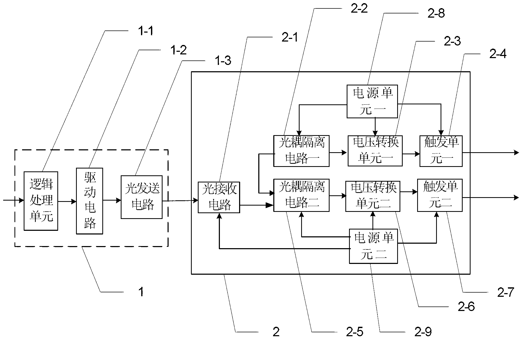
[0028] Specific implementation mode one: see figure 2 Describe this embodiment, the trigger device for the thyristor valve group of high-voltage TSC described in this embodiment, the trigger device includes A phase trigger device, B phase trigger device and C phase trigger device, and the A phase trigger device, B phase trigger device The structure of the triggering device and the c-phase triggering device are exactly the same, wherein, the A-phase triggering device is composed of a control unit 1 and a triggering device 2,

[0029] The control signal output end of the control unit 1 is connected with the control signal input end of the trigger device 2 through an optical fiber,

[0030] The control unit 1 includes a logic processing unit 1-1, a drive circuit 1-2 and an optical transmission circuit 1-3,

[0031] The signal input end of the logic processing unit 1-1 is used as the control signal input end of the control unit 1, and the signal output end of the logic processin...

specific Embodiment approach 2

[0040] Embodiment 2: This embodiment is a further limitation of the triggering device for a thyristor valve group of a high-voltage TSC described in Embodiment 1. The logic processing unit 1-1 is realized by a programmable logic device CPLD.

[0041] In this embodiment, the programmable logic device CPLD is used to realize the function of the logic processing unit. While meeting the logic operation requirements, it has the characteristics of low cost and low power consumption, which is beneficial to reduce capital investment. The processor device is highly integrated and has the function of realizing special application through user programming, which can greatly shorten the development cycle of the system. The pins TMS, TDI, TCK and TDO are respectively test mode selection, test clock, test data input and test data Output, the CPLD can be programmed, debugged and programmed online through these 4 pins.

specific Embodiment approach 3

[0042] Specific implementation mode three: see Figure 4 Describe this embodiment. This embodiment is a further limitation of the trigger device for the thyristor valve group of the high-voltage TSC described in the first or second embodiment. The drive circuit 1-2 is an amplifier circuit composed of two PNP transistors , the signal output end of the logic processing unit 1-1 is connected to one end of the resistor R20 and one end of the resistor R40 at the same time, and the other end of the resistor R40 is connected to the base of a transistor Q20, and the emitter of the transistor Q20 is connected to the resistor One end of R10 is connected, and the other end of resistor R10 is connected with the base of the one transistor Q10, and the emitter of the one transistor Q10 is connected with the power supply Vcc and the other end of the resistor R20 at the same time, and the collector of the other transistor Q20 is connected with the resistor One end of the R70 is connected, the...


PUM


Abstract

The invention discloses a triggering device and a triggering control method for a thyristor valve block of a high-voltage TSC (thyristor switched capacitor), and belongs to the field of electric system controllers. With the triggering device and the triggering control method, the problems of complex structures of existing triggering devices and complexity of existing triggering control methods are solved. A control unit is connected with the triggering device. The triggering control method includes that an external clock circuit is adopted to provide clock signals to a logical processing unit, collected SIN signals are judged to acquire switching time, switching signals are outputted according to the switching time, and the switching signals are converted to optical signals through a light transmission circuit to be outputted to a light receiving circuit after being amplified by a driving circuit; and the light receiving circuit outputs electric pulse signals to an optical-coupling isolation circuit II, and input sides of two optical-coupling isolation circuits are switched on simultaneously when the electric pulse signals are of low levels, so that two triggering signals are outputted by two triggering units to gate poles of the thyristor valve block of the high-voltage TSC simultaneously. The triggering device and the triggering control method are applicable to electric systems and industrial systems.

Description

technical field [0001] The invention belongs to the field of power system controllers, and in particular relates to a trigger device and a trigger control method for a thyristor valve group of a high-voltage TSC. Background technique [0002] At present, my country's power line loss structure is 220kY, 110kV, 35kV and 10kV. According to the analysis of relevant data, the reactive power load of the power system at this stage is about 1.3 times the active power, and the value continues to increase. If the reactive power cannot be compensated locally, the reactive power required by the user load will be provided by the long-distance power generation and distribution equipment, which will make the power distribution, transmission and power generation facilities unable to fully play their roles, and reduce the power generation and transmission costs. Ability to deteriorate the power supply quality of the power grid, and may cause the system voltage to collapse in severe cases, ca...

Claims


Application Information

Patent Timeline
Patent Type & Authority Applications(China)
IPC IPC(8): H02J3/18H03K17/06H03K17/722
CPCY02E40/12Y02E40/10
Inventor 李国勇
Owner 黑龙江特通电气股份有限公司
Why Eureka
Try Eureka