Multi-function transceiving circuit

A multi-functional circuit and circuit technology, applied in electrical components, transmission systems, etc., can solve the problem that the separate single-function MMIC circuit cannot meet the requirements of miniaturization and batch engineering, and achieve high temperature stability requirements and high power added. Efficient, complex effects with integrated functions

Active Publication Date: 2013-08-07
THE 13TH RES INST OF CHINA ELECTRONICS TECH GRP CORP
View PDF6 Cites 2 Cited by
  • Summary
  • Abstract
  • Description
  • Claims
  • Application Information

AI Technical Summary

Problems solved by technology

[0003] With the requirements of high power output, miniaturization and batching of phased array T / R components, the separate single-function MMIC circuits currently used in this system cannot meet the requirements of miniaturization and batch engineering

Method used


Image

  • Multi-function transceiving circuit
  • Multi-function transceiving circuit
  • Multi-function transceiving circuit

Examples


Embodiment Construction

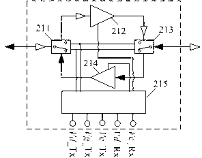
[0024] Such as figure 1 and 5 As shown, a multi-function integrated transceiver circuit includes an antenna end channel selection switch circuit 211, a receive channel low noise amplifier circuit 212, a drive end channel selection switch circuit 213, a transmit channel power amplifier circuit 214 and a transceiver branch power supply control circuit 215 . The low-noise amplifier circuit 212 of the receiving channel and the power amplifier circuit 214 of the transmitting channel are current multiplexing circuits, and the channel selection switch circuit 211 at the antenna end and the channel selection switch circuit 213 at the driving end use switch floating circuits.

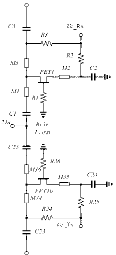
[0025] Such as figure 2 As shown, the antenna end channel selection switch circuit includes resistors R1-R3, resistors R24-R26, capacitors C1-C3, capacitors C23-C25, microstrip lines M1-M3, microstrip lines M34-M36 and field effect transistor FET1 And field effect tube FET10. The first path of the bidirect...


PUM


Abstract

The invention discloses a multi-function transceiving circuit, and relates to the technical field of transceiver circuits. The multi-function transceiving circuit comprises an antenna-end channel selecting switching circuit, a receiving channel low-noise amplifier circuit, a driving-end channel selecting switching circuit, a transmitting channel power amplifier circuit and transceiver branch power source controlling circuit. The receiving channel low-noise amplifier circuit and the transmitting channel power amplifier circuit are current reuse circuits. The antenna-end channel selecting switching circuit and the driving-end channel selecting switching circuit are adopted switch floating circuits. The multi-function transceiving circuit is characterized by complex integrated functions, ultra-low power consumption, high power addition efficiency, high requirements on temperature stability and the like. As combined with the chip processing technique characteristics, varied novel technologies such as current reuse technology of amplifiers and float switches are employed innovatively, various specified requirements of ultra-low power of receiving braches and high power addition efficiency of transmitting branches are met, the whole circuit topology for different application backgrounds is optimized and innovated, and various indicators are achieved.

Description

technical field [0001] The invention relates to the technical field of dual-purpose circuits for transmitting and receiving, in particular to the technical field of a microwave monolithic integrated circuit. Background technique [0002] The high power added efficiency transceiver integrated multifunctional circuit is widely used in microwave and millimeter wave phased array systems as a component, Figure 11 It is a schematic diagram of a simplified phased array T / R component. The system includes a transceiver integrated multifunctional circuit 210 and an amplitude and phase control multifunctional circuit 220. The two multifunctional circuits implement a phased array T / R unit to realize Sending and receiving amplification function and amplitude and phase control of transmission signal. The transceiver integrated multifunctional circuit 210 includes five functional units including an antenna-side channel selection switch circuit 211, a receive channel low-noise amplifier ci...

Claims


Application Information

Patent Timeline
IPC IPC(8): H04B1/40
Inventor 方园吴洪江韩芹高学邦刘永强刘如青李富强曾志王向玮崔玉兴魏洪涛
Owner THE 13TH RES INST OF CHINA ELECTRONICS TECH GRP CORP
Why Eureka
Try Eureka