Cap beam efficient, convenient and quick to construct and construction method thereof

A construction method, cap beam technology, applied in the direction of bridges, bridge parts, bridge construction, etc., can solve the problems of difficult construction quality control of high supports, a large amount of manpower and material resources, and high construction costs, so as to save the construction time , environmental protection science, and the effect of providing work efficiency

Inactive Publication Date: 2013-08-14
SHANGHAI CIVIL ENG GRP FIFTH
View PDF4 Cites 15 Cited by
  • Summary
  • Abstract
  • Description
  • Claims
  • Application Information

AI Technical Summary

Problems solved by technology

The traditional cap beam construction of bridge piers usually starts with pier column construction, then builds brackets to install cap beam formwork, and then carries out concrete construction. In this process, a lot of manpower and material resources are invested in the erection of brackets and the reinforcement of formwork. Therefore, the support method construction has the following Defects: (1) Compulsory measures such as foundation treatment are often required for the erection of supports. The construction of urban bridges on existing roads will seriously affect the normal passage of various vehicles on the roads, which brings great inconvenience to traffic; (2) A lot of manpower and material resources must be invested in the support construction, resulting in high construction costs; (3) The input cost is relatively large, and there are many control procedures, especially the construction quality control of high supports is difficult, and installation and disassembly are difficult; (4) The construction period is long, Heavy noise pollution and many uncontrollable factors

Method used


Image

  • Cap beam efficient, convenient and quick to construct and construction method thereof
  • Cap beam efficient, convenient and quick to construct and construction method thereof
  • Cap beam efficient, convenient and quick to construct and construction method thereof

Examples


Embodiment Construction

[0028] Below in conjunction with accompanying drawing, the present invention will be further described:

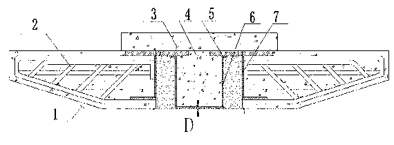
[0029] figure 1 As shown, it is a schematic diagram of the front structure of the cap beam 1, which includes a cap beam steel skeleton 2 and a cap beam embedded part 3. In the middle of the cap beam steel skeleton 2, a cap beam embedded part 3 is provided; 2 is filled with poured concrete.

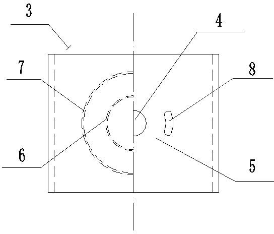
[0030] combine figure 2 As shown, it is a structural schematic diagram of the top view of the embedded part 3 of the cap beam, and it can be seen by cutting half of the top plate 5: the embedded part 3 of the cap beam includes the outer ring steel pipe 7, the inner ring steel pipe 6 and the top plate 5; wherein, the outer ring steel pipe 7 is arranged on the outside of the inner ring steel pipe 6, and the tops of the outer ring steel pipe 7 and the inner ring steel pipe 6 are fixedly connected with the bottom surface of the top plate 5; the bottom surface of the inner ring steel pip...


PUM


Abstract

The invention discloses a cap beam which is efficient, convenient and quick to construct, and the cap beam comprises a cap-shaped cap beam reinforcement cage and is characterized in that a cap beam embedded part is arranged in the middle of the cap beam reinforcement cage. An erection method of the cap beam comprises the following steps of manufacturing the cap beam, performing pier column construction, embedding prestressed reinforcements and splined hole steel pipes, hoisting the prefabricated cap beam to the top of a pier column with hoisting equipment, connecting the prefabricated cap beam with the prestressed reinforcements, tensioning the prestressed reinforcements, concreting and grouting the cap beam embedded part of the prefabricated cap beam, and concreting and closing the top ends of the prestressed reinforcements. The cap beam and the method give full play to the advantages of cap beam construction; the pier column is effectively and fixedly connected with the cap beam by adopting the prestressed reinforcements and the splined hole steel pipes; the prefabricated cap beam is hoisted directly, so that treatment on a foundation is reduced; the existing road traffic pressure is reduced; the support erection time is saved; the construction period is shortened; and in short, the method is more scientific in working efficiency, economy, environmental protection and the like in comparison with the currently adopted method.

Description

technical field [0001] The invention relates to a building component and a construction method thereof, in particular to a bridge pier cap beam and a construction method thereof. Background technique [0002] With the rapid development of traffic, a large number of highway bridges, railway bridges, and municipal bridges are in urgent need of construction. In order to speed up the construction progress and ensure the quality of the project, the construction unit usually adopts relevant safety protection measures in the construction of the bridge pier cap beam. The traditional cap beam construction of bridge piers usually starts with pier column construction, then builds brackets to install cap beam formwork, and then carries out concrete construction. In this process, a lot of manpower and material resources are invested in the erection of brackets and the reinforcement of formwork. Therefore, the support method construction has the following Defects: (1) Compulsory measures ...

Claims


Application Information

Patent Timeline
Patent Type & Authority Applications(China)
IPC IPC(8): E01D19/02E01D21/00
Inventor 唐俊刘明友
Owner SHANGHAI CIVIL ENG GRP FIFTH
Why Eureka
Try Eureka