A large turbocharged two-stroke diesel engine with exhaust gas purification

A diesel engine, turbocharged technology, applied in engine components, combustion engines, machines/engines, etc., can solve the problems of overall head loss, bulkiness, limitations, etc. of the exhaust system

Active Publication Date: 2013-08-14
曼能解决方案(曼能解决方案德国股份公司)分公司
View PDF7 Cites 10 Cited by
  • Summary
  • Abstract
  • Description
  • Claims
  • Application Information

AI Technical Summary

Problems solved by technology

[0010] Against this background, it has been proposed to provide SCR systems with complex and thus expensive injection systems for homogeneous distribution of ammonia or urea in the exhaust gas flow and in order to ensure sufficient mixing downstream using special so-called hybrid units, which are usually quite large and bulky
Also, the mixing unit contributes to the overall head loss (pressure loss) of the exhaust system and it equates to a reduction in turbocharger efficiency
In particular, the loss of efficiency in turbochargers is unsatisfactory from the point of view of fuel efficiency
Furthermore, this pressure loss limits the applicability of power turbines driven by wastegate flow (Waste heat recovery - WHR)

Method used


Image

  • A large turbocharged two-stroke diesel engine with exhaust gas purification
  • A large turbocharged two-stroke diesel engine with exhaust gas purification
  • A large turbocharged two-stroke diesel engine with exhaust gas purification

Examples


Embodiment Construction

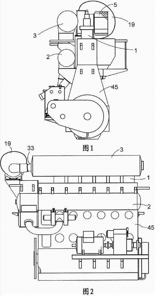
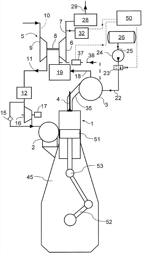
[0042] In the following detailed description, a large two-stroke engine will be described by means of an exemplary embodiment. Figure 1 to Figure 3 A large low speed turbocharged two stroke diesel engine with crankshaft 52 and crosshead 53 is shown. image 3 A diagram showing a large low-speed turbocharged two-stroke diesel engine with its intake and exhaust systems. In this exemplary embodiment, the engine has six cylinders 1 arranged in a straight line. Large turbocharged two-stroke diesel engines typically have cylinders of five and six in a linear arrangement supported by the engine frame 45 . The engine may eg be used as the main engine in an ocean-going vessel or as a stationary engine in a power plant for operating a generator. The total output of the engine may for example be in the range between 5,000 kW to 110,000 kW.

[0043] The engine is two-stroke direct-scavenging with a scavenging port at the lower region of cylinder 1 and an exhaust valve 4 at the top of c...


PUM


Abstract

A large turbocharged two-stroke diesel engine with crossheads, said engine having a plurality of cylinders (1) in line, a turbocharger (5) and an SCR reactor (19) upstream of the turbocharger and downstream of an exhaust gas receiver (3) . The exhaust gas receiver (3) is connected to the individual cylinders (1) via respective exhaust ducts (35) that introduce the exhaust gas tangentially and cause a swirl in the exhaust gas inside the exhaust gas receiver (3) . The exhaust gas receiver (3) is provided with an outlet (33) . A unit (42) with plurality of vanes (43) around a central axial duct (47) divides the exhausts gas receiver (3) in a mixing section (48) downstream of the unit and an outlet section (49) upstream of the unit (42) The swirling exhaust gas passes along the vanes (43) on its way from the inixing section (48) to the outlet section (49) and the vanes (43) cause the exhaust gas to lose its swirl and gain pressure. The pressure gain causes a portion of the exhaust gas in the outlet section (49) to flow back to the mixing section (48) via said central duct (47) . The reductant is introduced in the flow in said central duct 47) . A large turbocharged two-stroke diesel engine with an exhaust gas receiver (3) with tangential inlets (35) and a tangential outlet (39) is also disclosed It is suggested that Fig. 4 is published with the abstract.

Description

technical field [0001] The present invention relates to a crosshead large turbocharged two-stroke internal combustion piston engine, preferably a diesel engine with an exhaust gas purification system, in particular, the present invention relates to a diesel engine with a system for purifying NO in the exhaust gas x (nitrogen oxides) SCR (Selective Catalytic Reduction, Selective Catalytic Reduction) reactor crosshead large two-stroke diesel engine. Background technique [0002] Large crosshead two-stroke engines are commonly used in the propulsion systems of large ships or as prime movers in power stations. In particular, for nitrogen oxides (NO x ) levels, the emission requirements have been or will become increasingly difficult to meet. [0003] General awareness of environmental issues is growing rapidly. Emission limits in the form of air pollution at sea are now being discussed within the IMO (International Maritime Organisation). Authorities in various parts of the ...

Claims


Application Information

Patent Timeline
Patent Type & Authority Applications(China)
IPC IPC(8): F01N3/20F02B37/02
CPCY02T10/144Y02T10/12E06B3/267E04B2/88E06B3/24E06B3/67E06B2003/26321
Inventor 卡尔-约翰·内根米尔
Owner 曼能解决方案(曼能解决方案德国股份公司)分公司
Why Eureka
Try Eureka