Carbon dioxide hydrate slurry cold storing and releasing central air conditioning unit

A technology of carbon dioxide and hydrate slurry, which is applied in air-conditioning systems, space heating and ventilation, household heating, etc., can solve the problems of lack of cold storage function of cooling devices, small size of hydrate reactors, and inability to provide driving energy. Achieve the effect of saving electricity expenses, reducing energy consumption, and even and more thorough hydration reaction

Inactive Publication Date: 2013-08-14
UNIV OF SHANGHAI FOR SCI & TECH
View PDF6 Cites 6 Cited by
  • Summary
  • Abstract
  • Description
  • Claims
  • Application Information

AI Technical Summary

Problems solved by technology

Its device makes full use of the latent heat of hydrate and the high-pressure gas formed by its decomposition, and has the characteristics of high efficiency, simple structure, and convenient operation. When the pressure of the high-pressure gas cylinder is reduced, it cannot provide enough driving energy and the pressure required for hydrate formation; the patent No. 200820056062.4 titled "A Visualization Device for Gas Hydrate Cold Storage / Gas Storage" discloses a A visualization device with cold storage function
The device uses stirring and a constant temperature water bath to reduce the time for hydrate formation. The driving energy is also a high-pressure cylinder, so the device cannot run for a long time, and the device lacks a cooling device and only serves as a cold storage function. The hydrate reactor The size is small, the cold storage capacity is small, and it cannot meet the cooling capacity requirements of a larger space; the patent number is 201210137361 and the name is "A CO 2 Hydrate Slurry Circulation Cold Storage and Release Type Automobile Air Conditioning Device” patent discloses a CO-based 2 Hydrate slurry cold storage and release automotive air-conditioning device, which uses two hydration reactors to simultaneously store cold and release cold, and uses a throttle valve to control CO 2 To cool down
The structure of the device is complex, the cost is high, and further optimization is required

Method used


Image

  • Carbon dioxide hydrate slurry cold storing and releasing central air conditioning unit

Examples


Embodiment Construction

[0017] The following embodiments describe the present invention in detail in conjunction with the accompanying drawings.

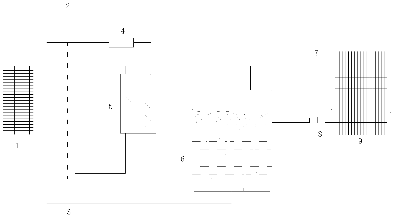
[0018] figure 1 Is a kind of CO of the present invention 2 Schematic diagram of the structure of the central air-conditioning device for cold storage and release of hydrate slurry.

[0019] Such as figure 1 As shown, this example involves CO 2 The central air-conditioning device for cold storage and release of hydrate slurry includes the following parts: compressor 2, cooler 1, regenerator 5, expander 3, hydration reactor 6, air cooler 9, control valve 8 and circulation pump 7. The exhaust port of the compressor 2 is connected with the inlet of the cooler, the outlet of the cooler is connected with the expander, and the outlet of the expander is connected with the diffuser orifice plate at the bottom of the hydration reactor, wherein the expander 3 and the compressor 2 pass through a coupling Linkage, CO 2 When the gas expands, it drives the coupling,...


PUM


Abstract

A carbon dioxide hydrate slurry cold storing and releasing central air conditioning unit comprises a compressor, a cooler, a heat regenerator, an air cooler, a valve, a circulating pump, an expansion machine and a hydration reaction kettle. The expansion machine is used for producing carbon dioxide gas to a carbon dioxide gas-liquid mixture through cooling and depressurization; the hydration reaction kettle is used for producing water and the carbon dioxide gas-liquid mixture to carbon dioxide hydrate slurry; the heat regenerator is communicated with the expansion machine; then the expansion machine is communicated with the hydration reaction kettle; an outlet of hydrate slurry of the hydration reaction kettle is communicated with an inlet of a fan coil of the air cooler through a control valve; an outlet of the fan coil of the air cooler is sequentially communicated with the circulating pump and a backflow inlet of the hydration reaction kettle; and a gas outlet of the hydration reaction kettle is sequentially communicated with the heat regenerator and a dryer and then communicated with an air suction port of the compressor.

Description

technical field [0001] The present invention relates to a novel carbon dioxide (hereinafter referred to as CO 2 Indicates) Hydrate slurry cold storage air-conditioning device. Especially involving a CO 2 The refrigerating machine technology in which the hydrate slurry is used as a cooling agent and a bridging agent belongs to the technical fields of refrigeration engineering and chemical engineering. Background technique [0002] With the development of the economy and the improvement of people's living standards, people have put forward higher requirements for the working and living environment. Many shopping malls, hotels, office buildings, and residential buildings are equipped with air-conditioning systems, which has led to a very rapid growth in my country's electricity demand, especially the widening gap between peak and trough power consumption within a day, and the uneven operation of the power grid has become increasingly serious, which has greatly affected The co...

Claims


Application Information

Patent Timeline
Patent Type & Authority Applications(China)
IPC IPC(8): F24F5/00
Inventor 谢应明谢振兴范兴龙杨迟
Owner UNIV OF SHANGHAI FOR SCI & TECH
Why Eureka
Try Eureka