Electric machine used as motor in motor car

A technology for driving shafts and connecting components, which is applied in the direction of electromechanical devices, machines/engines, engine starting, etc., and can solve problems such as failure and drive shaft cracks

Active Publication Date: 2013-08-14
SEG AUTOMOTIVE GERMANY GMBH
View PDF5 Cites 1 Cited by
  • Summary
  • Abstract
  • Description
  • Claims
  • Application Information

AI Technical Summary

Problems solved by technology

If the axial force is further increased, it may cause the drive shaft to form cracks and fail, especially when assembling the motor

Method used


Image

  • Electric machine used as motor in motor car
  • Electric machine used as motor in motor car
  • Electric machine used as motor in motor car

Examples


Embodiment Construction

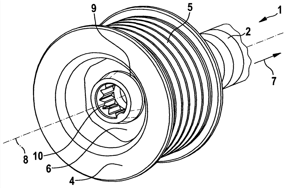
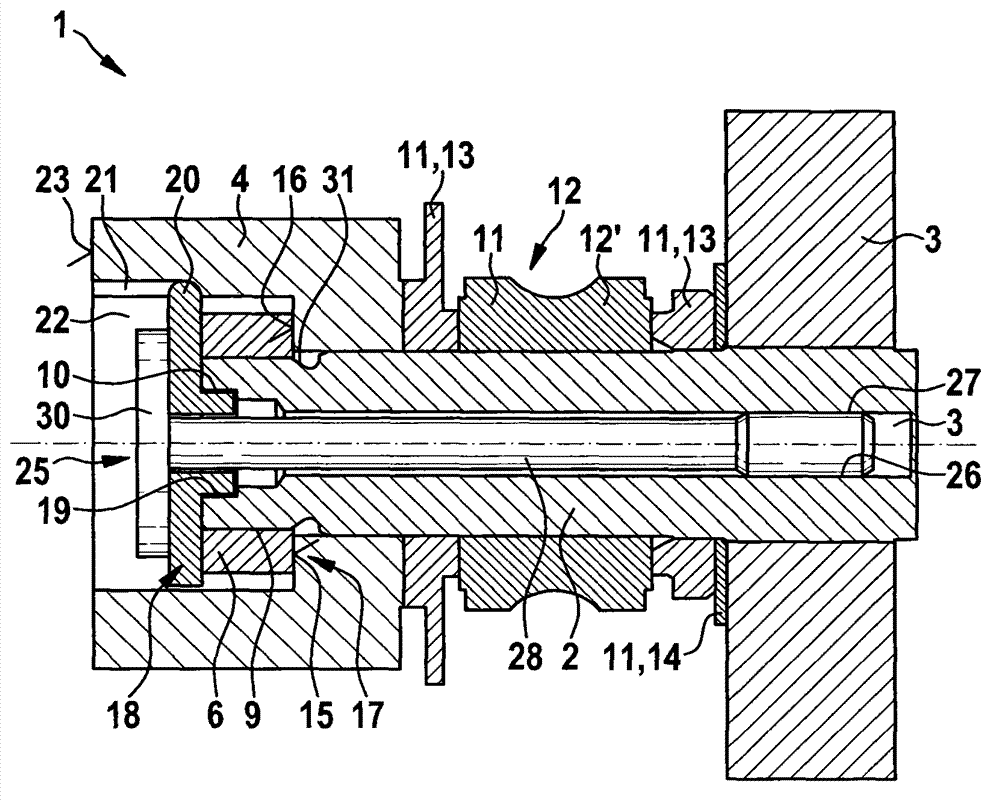
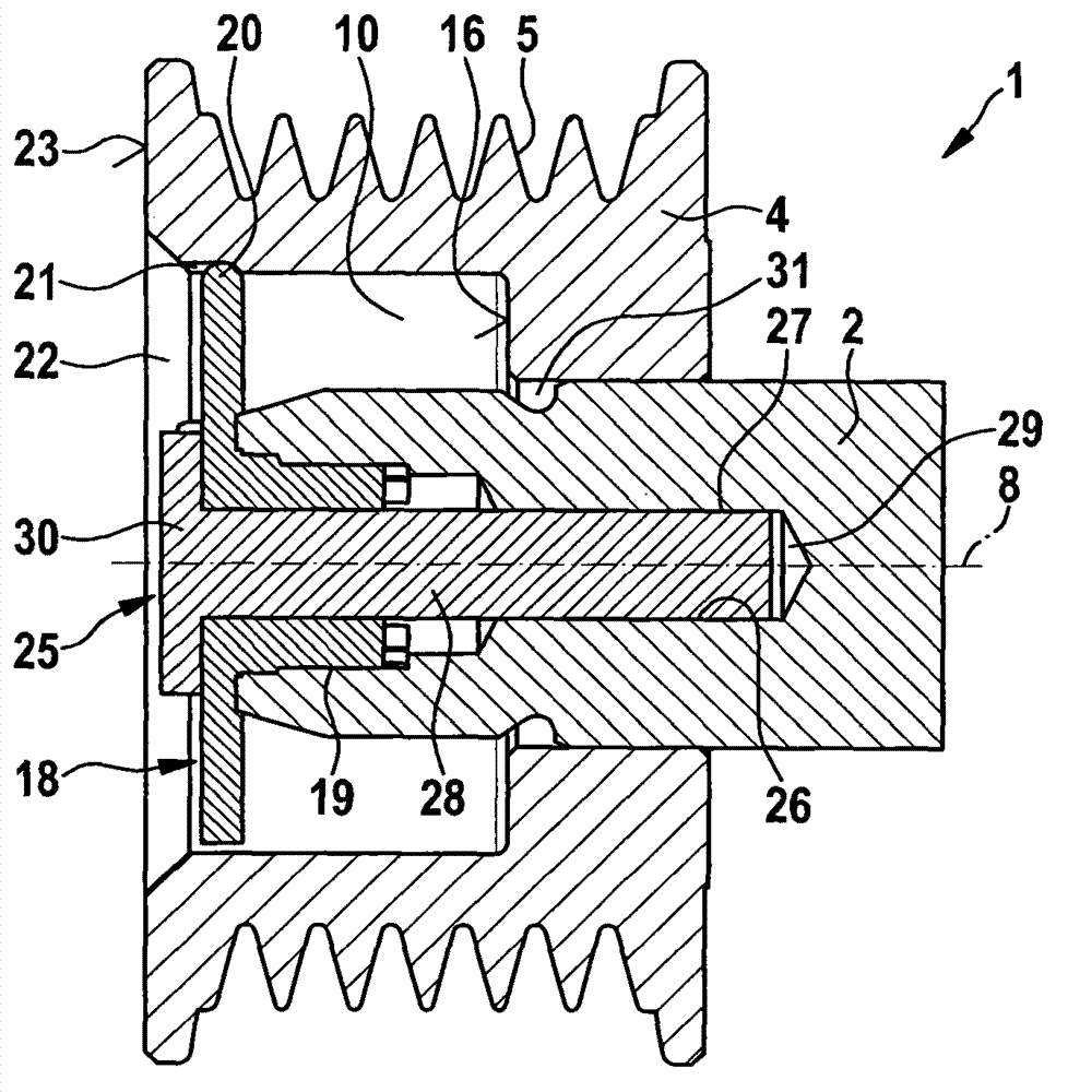
[0027] figure 1 A partial view of a conventional electric machine 1 is shown. The electric machine 1 can be used, for example, as a motor, a generator or also as a motor-generator. It has a drive shaft 2 through which the motor can give or receive torque. A rotor 3 (not shown here) and a coupling element 4 preferably spaced from the rotor 3 in the axial direction are arranged on the drive shaft 2 . The coupling element 4 serves, for example, as a pulley, ie has a revolving surface 5 for bending a flexible winding means, such as a belt. The coupling element 4 is fastened to the drive shaft 2 by means of a fastening element 6 and is pressed by the fastening element in the direction of the rotor 3 , ie in the direction of the arrow 7 . The arrow 7 is here parallel to the longitudinal axis 8 or the axis of rotation of the drive shaft 2 .

[0028] The securing element 6 is in the form of a nut, which is screwed onto the outer shaft thread 9 of the drive shaft 2 , which is only ...


PUM


Abstract

The electric machine (1) has a drive shaft (2) on which a rotor (3) and a connector (4) are arranged. A partial actuated torque transmission connection between the rotor and the connector is formed in drive shaft. An attachment element (6) is provided for axially defining the connector into the direction turned away from the rotor. The drive shaft and the connector are made in active connection with a connector (18). An external teeth (19) of connector is engaged with an internal gear (10). An independent claim is included for assembly method of electric machine.

Description

technical field [0001] The invention relates to an electric machine with a drive shaft, on which a rotor and a coupling element are arranged, and in which an at least partially force-locking torque-transmitting connection is formed between the rotor and the coupling element, for this purpose at least at a distance from the coupling element. In the direction of the rotor there are fixing elements for axially fixing the coupling elements. The invention also relates to a method for assembling an electric machine. Background technique [0002] Electric machines of the type described above are known from the prior art. The electric machine can be designed in various forms and can be used in particular as a motor, generator or motor-generator of a motor vehicle. The electric motor has a drive shaft through which the electric motor gives or receives torque. The rotor and the coupling element are at least partially arranged on the drive shaft. The rotor is supported in the elect...

Claims


Application Information

Patent Timeline
Patent Type & Authority Applications(China)
IPC IPC(8): H02K7/10
CPCH02K7/108H02K7/003B60K25/02F02B67/06F02N11/04F02N15/08F16C19/06F16C35/063F16C2380/26F16D1/10F16H7/02F16H55/36
Inventor M·亨格
Owner SEG AUTOMOTIVE GERMANY GMBH
Why Eureka
Try Eureka