Multiphase current-sharing controlled parallel-connection adjusting circuit and control method

A technology of adjusting circuit and flow control, applied in the direction of conversion equipment with intermediate conversion to AC, can solve the problem of beat frequency, difficult to filter low-frequency harmonics, current ripple cannot be effectively reduced, etc., to improve reliability. , High efficiency power density, the effect of reducing the volume of magnetic components

Active Publication Date: 2013-08-14
SHANGHAI ELECTRIC POWER ELECTRONICS
View PDF3 Cites 52 Cited by
  • Summary
  • Abstract
  • Description
  • Claims
  • Application Information

AI Technical Summary

Problems solved by technology

However, for resonant circuits such as LLC, because they adopt frequency modulation control, when the two-phase LLC circuits operate at different frequencies in order to achieve

Method used


Image

  • Multiphase current-sharing controlled parallel-connection adjusting circuit and control method
  • Multiphase current-sharing controlled parallel-connection adjusting circuit and control method
  • Multiphase current-sharing controlled parallel-connection adjusting circuit and control method

Examples


Embodiment 1

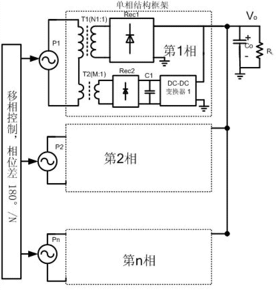
[0030] Embodiment 1: Embodiment 1 includes an N-phase parallel adjustment circuit, wherein the input of the first phase is an AC source P1, and the structure frame of the first phase includes two transformers T1 and T2, a rectification structure Rec1 and Rec2, and a DC-DC converter 1. The input capacitor C1 and the output capacitor Co of the DC-DC converter. The ratio of primary turns to secondary turns of transformer T1 is N1:1, and the ratio of primary turns to secondary turns of transformer T2 is M:1. The primary windings of T1 and T2 are connected in series to both ends of the input AC side P1. The secondary winding of T1 is connected to the input end of the secondary rectification structure Rec1, and one end of the output of Rec1 is connected to the positive end of the output capacitor, and the other end is connected to the negative end of the output Vo. The secondary winding of T2 is connected to the input terminal of the secondary rectification structure Rec2, and the ...

Embodiment 2

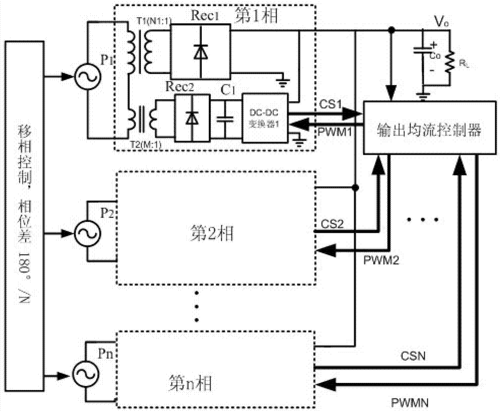
[0031] Embodiment 2: Embodiment 2 is for figure 1 The proposed topology implements an embodiment of a control method for multiphase current sharing. The control method implemented by the controller can be implemented using analog or digital methods. The functions realized by the controller include the driving of the switching tube of the primary side inverter structure, the driving of the secondary side DC-DC converter and the feedback control of the converter. The shifting control is adopted between the N phases of the primary side of the converter, the phase difference between two adjacent phases is 180° / N, and the driving frequency and duty cycle of multiple phases are the same. The driving signals of the N-phase DC-DC converter on the secondary side are PWM1 to PWMN, and each phase is synchronous with the corresponding primary side. Frequency and duty cycle are regulated by the controller. The feedback control includes a voltage loop and a current loop, and the sampled...

Embodiment 3

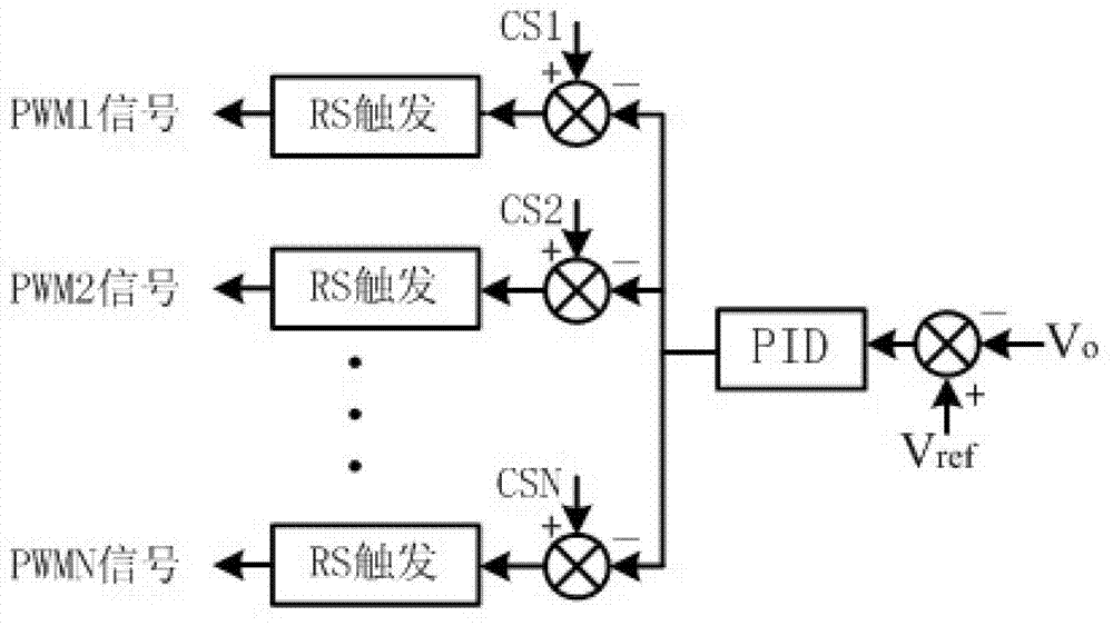
[0032] Embodiment 3: Embodiment 3 is a control method proposed on the basis of Embodiment 2 that can realize multi-phase equal flow tightness adjustment. The method adopts the peak current mode to realize the feedback control of the DC-DC converter module. The feedback signals to be sampled include the output voltage Vo and the current waveform signals CS1 to CSN of the power switch tubes in each phase of the DC-DC converter. The error signal obtained by subtracting the reference voltage Vref from the converter output voltage Vo is amplified by the compensation network (PID) as the common modulation signal of the PWM modulator, and the current signal CS1-CSN flowing through the switching device is used as the carrier signal of each phase . After CSN is subtracted from the modulating signal, after the RS flip-flop, at the beginning of each switching cycle, the RS flip-flop is set by the clock pulse, and then the inductor current gradually increases. When the current signal CSN...


PUM


Abstract

The invention relates to the field of direct current (DC)/DC conversion and rectification, and aims to provide a multiphase current-sharing controlled parallel-connection adjusting circuit and a control method. The circuit comprises n phases of adjusting circuits connected in parallel, the structure of each phase of the adjusting circuits are identical; each phase comprises a main transformer and an auxiliary transformer; a primary side winding of the master transformer and a primary side winding of the auxiliary transformer in each phase of circuits are connected in series and then connected in parallel to two ends of an equivalent alternating input power supply PN; secondary side windings of the main transformers in two outputs penetrate through the rectification circuit and then are directly connected to the right end of a current device output side, and the other end is grounded; a secondary winding of the auxiliary transformer in another circuit penetrates through the rectification circuit and then is connected to the input end of a DC-DC converter, and the output end of the DC-DC converter is connected in parallel to the current device output side. Current sharing among multipath transformers is achieved by controlling the balance of power of a small-power DC-DC module; the feedback is realized on a secondary side, the feedback signal can be transmitted to a primary side without isolation, and the system reliability is improved.

Description

technical field [0001] The invention belongs to the field of DC / DC conversion and rectification, and relates to a parallel adjustment circuit capable of realizing multi-phase current sharing and a control method thereof. More specifically, the present invention relates to a multi-phase parallel adjustment circuit, which can realize the current sharing of the whole circuit by controlling the current of the parallel-connected low-power modules. Background technique [0002] Multi-phase interleaved parallel technology can reduce output current ripple, reduce output capacitor volume, optimize heat and power distribution, and has been widely used in medium and high power applications. However, due to the deviation of the circuit load characteristics and the control parameters, the current deviation of the two or more loads will be caused, and the current ripple cannot be effectively reduced. Therefore, it is necessary to increase the current sharing measures to ensure the current...

Claims


Application Information

Patent Timeline
IPC IPC(8): H02M3/28
Inventor 吴新科陈慧
Owner SHANGHAI ELECTRIC POWER ELECTRONICS
Why Eureka
Try Eureka