Temperature compensating circuit and temperature compensating method for switch-type Hall sensor

A technology of temperature compensation circuit and Hall sensor, which is applied in the field of temperature compensation of switch-type Hall sensor and temperature compensation circuit of switch-type Hall sensor. and other problems, to achieve the effect of high temperature compensation accuracy, lower requirements, and relax the selection surface

Active Publication Date: 2013-08-14
CROSSCHIP MICROSYST
View PDF8 Cites 19 Cited by
  • Summary
  • Abstract
  • Description
  • Claims
  • Application Information

AI Technical Summary

Problems solved by technology

However, in practice, due to the non-linearity of the temperature coefficient of resistance, the compensation error of this scheme is relatively high, and it is impossible to achieve indiscriminate compensation at every temperature value.
In the production process of integrated circuits, affected by the precision of process control, the resistance value of different batches will have certain differences. Since the traditional compensation circuit uses two kinds of resistors with positive and negative temperature coefficients, the compensation effect is directly related to the resistance value. relationship, so traditional schemes are susceptible to process

Method used


Image

  • Temperature compensating circuit and temperature compensating method for switch-type Hall sensor
  • Temperature compensating circuit and temperature compensating method for switch-type Hall sensor
  • Temperature compensating circuit and temperature compensating method for switch-type Hall sensor

Examples


Embodiment Construction

[0033] Through the following description of the embodiments, it will be more helpful for the public to understand the present invention, but the specific embodiments given by the applicant cannot and should not be regarded as limitations on the technical solutions of the present invention, any components or technical features Changes to the definition and / or formal but not substantive changes to the overall structure should be regarded as the scope of protection defined by the technical solutions of the present invention.

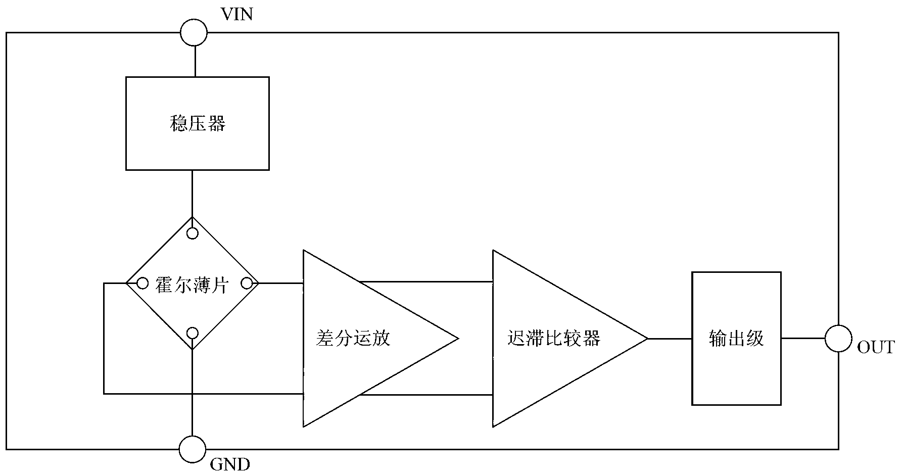
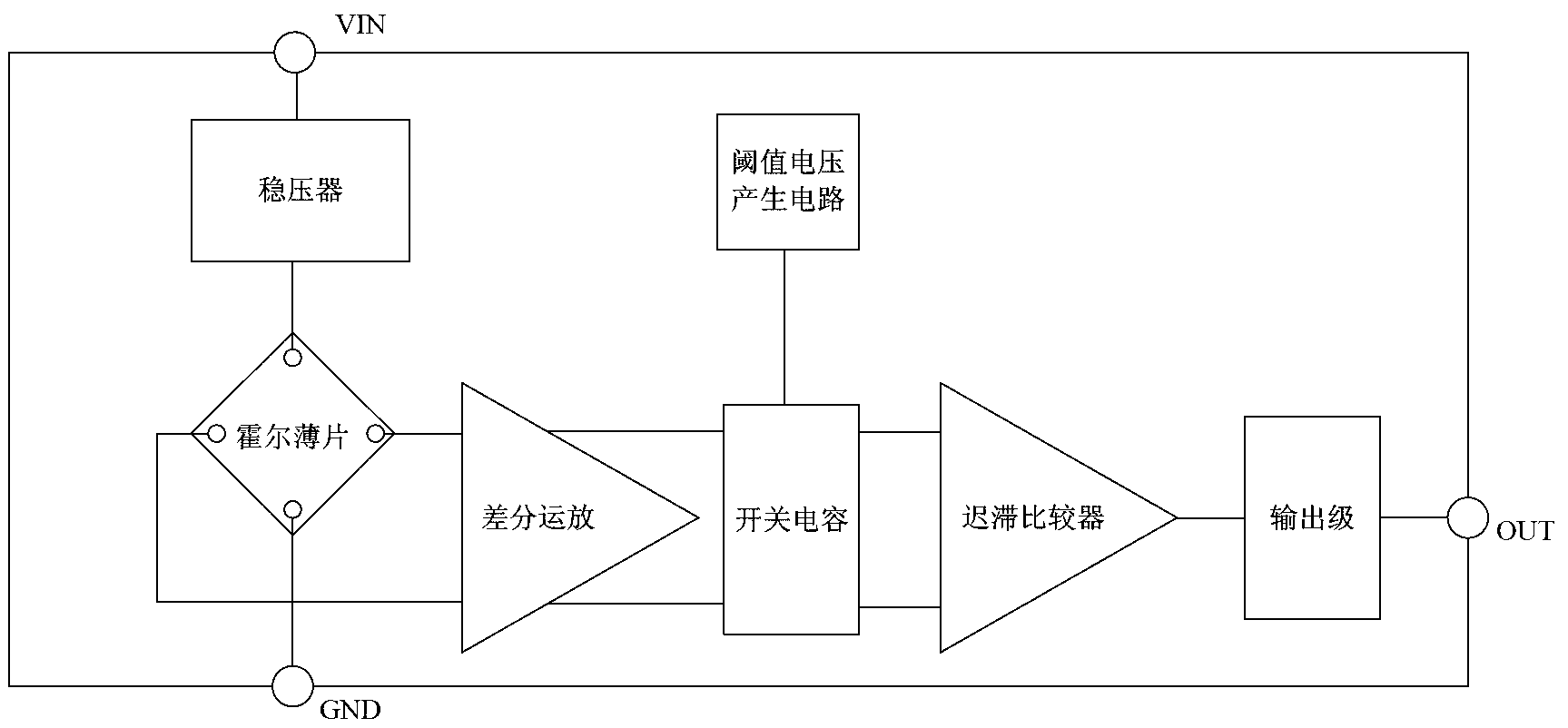
[0034] A temperature compensation circuit for a switch-type Hall sensor, including: a Hall sheet, used to convert the signal of the induced magnetic block into a voltage signal; a differential amplifier, used to amplify the Hall voltage; a switched capacitor The circuit is used to eliminate the offset of the amplified Hall signal; a voltage regulator is used to convert the external voltage into a stable internal working voltage and provide it to other circui...


PUM

PropertyMeasurementUnit
Temperature coefficientaaaaaaaaaa

Abstract

The invention discloses a temperature compensating circuit and a temperature compensating method for a switch-type Hall sensor. The temperature compensating circuit comprises a Hall chip, a differential amplifier, a switched capacitor circuit, a voltage stabilizer and a hysteresis comparator, wherein a reference current generating circuit and a threshold voltage generating circuit are connected in series between the voltage stabilizer and the switched capacitor circuit, and are used for generating reference current and threshold voltage to be provided to the hysteresis comparator; and the hysteresis comparator is used for comparing an amplified Hall induced voltage with a threshold voltage value, and outputting a discrimination result to an output stage. According to the temperature compensating circuit and the temperature compensating method, the reference current generating circuit module is added, the threshold voltage generating way is changed, the temperature compensating accuracy is higher, the influence of nonlinearity of a resistance temperature coefficient is eliminated, undifferentiated high-accuracy compensation can be realized on each temperature value, the requirement on a used process line is lowered, a resistor of a specific positive-negative temperature coefficient is not needed, and the selection range of the process line is expanded for a design engineer.

Description

technical field [0001] The invention relates to a temperature compensation circuit, in particular to a temperature compensation circuit of a switch-type Hall sensor; the invention also relates to a temperature compensation method of a switch-type Hall sensor. Background technique [0002] The Hall sensor is a magnetic field sensor made according to the Hall effect. The Hall effect is a kind of magnetoelectric effect, which was discovered by the American scientist Hall in 1879 when he was studying the conductive mechanism of metals. Later, it was found that the Hall effect of semiconductors is much stronger than that of metals. This phenomenon is used to make various Hall elements, which are widely used in industrial automation, automotive electronics, consumer electronics and other fields. [0003] Pass a bias current I across both ends of the semiconductor sheet, and apply a magnetic field with a magnetic induction intensity B in the vertical direction of the sheet, then a...

Claims


Application Information

Patent Timeline
IPC IPC(8): H03K17/14H03K17/90
Inventor 彭卓陈忠志赵翔
Owner CROSSCHIP MICROSYST
Why Eureka
Try Eureka