Charge control device for electric vehicle

A charging control, electric vehicle technology, applied in battery/fuel cell control devices, control devices, electric vehicle charging technology, etc. The effect of complexity, prevention of enlargement, and cost reduction

Active Publication Date: 2013-08-14
HONDA MOTOR CO LTD
View PDF7 Cites 16 Cited by
  • Summary
  • Abstract
  • Description
  • Claims
  • Application Information

AI Technical Summary

Problems solved by technology

However, since the terminals for charging are divided into those for the normal charger and those for the fast charger, and are provided separately, the number of parts increases and the cost of the charging control device increases.
In addition, when the charger is installed in an electric two-wheeled vehicle in the form of a vehicle, it is different from a four-wheeled vehicle. In an electric two-wheeled vehicle, due to the limited space for configuring it, and considering issues such as the degree of freedom of the layout, the electric two-wheeled It is difficult to have on-board space to install the charger in a wheeled vehicle
[0005] Also, the terminals for normal charging and the terminals for rapid charging are provided separately, and when inserting the charging plug into the terminals, it is necessary to judge and select the inserted terminals, which makes the user feel cumbersome.
In addition, since the fast charger needs to use a large current to charge the battery compared with the normal charger, the terminal for the fast charger needs to use a terminal with a large power, which increases the cost.

Method used


Image

  • Charge control device for electric vehicle
  • Charge control device for electric vehicle
  • Charge control device for electric vehicle

Examples


Embodiment Construction

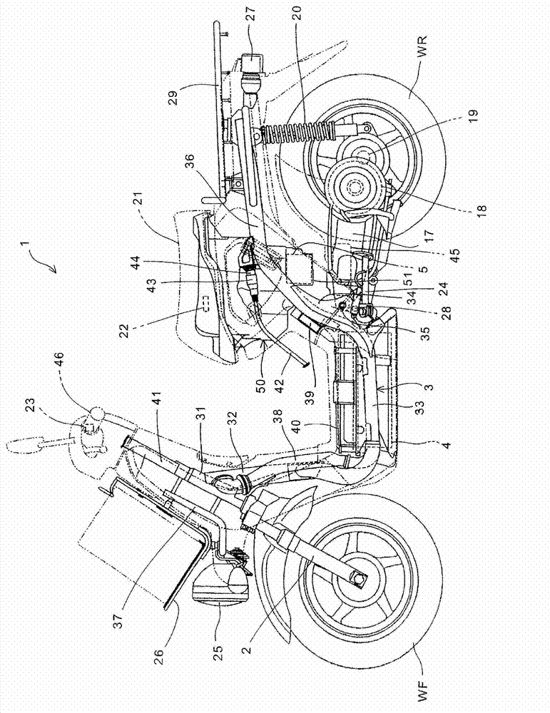
[0040] Hereinafter, an embodiment of the present invention will be described with reference to the drawings. figure 2 It is a left side view of an electric vehicle equipped with a charging control device according to an embodiment of the present invention. The electric vehicle 1 is a scooter-type two-wheeled vehicle with a low floor, and each component is mounted on a vehicle frame 3 directly or indirectly through other components. The vehicle frame 3 has: a head pipe 31; a front frame portion 32 whose top end is joined to the head pipe 31 and whose rear end extends downward; The left and right directions branch and extend to the rear of the vehicle body; the rear frame part 36 extends rearward from the main frame part 33 along the vehicle body.

[0041] The front fork 2 supporting the front wheel WF is supported on the head pipe 31 in a steerable manner. A steering shaft 41 extending upward from the front fork 2 is supported by the head pipe 31 , and a steering handle 46 h...


PUM


Abstract

The invention provides a charge control device for an electric vehicle. In the device, a common charging coupler for a normal charger and a quick charger are provided so as to improve the usability of the users and so as to simplify a charging system. A battery (4) supplies electric power to a motor (18) that is a driving source of an electric vehicle (1). A quick charger (10) comprises: a first charging circuit (52) that charges the battery (4); a second charging circuit (53) which is connected in parallel with the first charging circuit (52); and a charging coupler (13) for connecting the first charging circuit (52) and the second charging circuit (53) to the battery (4). The first charging circuit (52) and the second charging circuit (53) are connected to the battery (4) via common circuit portions (PLp, PLn) that are arranged between the charging coupler (13) and the battery (4). A normal charger is provided only with the first charging circuit (52) out of the first charging circuit (52) and the second charging circuit (53).

Description

technical field [0001] The invention relates to a charging control device for an electric vehicle, which is applicable no matter whether the vehicle is connected to a common charger or a fast charger, and can enable users to obtain good convenience in terms of usability. Background technique [0002] For electric vehicles that use the input voltage of the storage battery (battery) to drive the motor as the driving source, there are ordinary chargers and rapid chargers for charging the batteries. Since the currents supplied by the two are different from each other, in order to be compatible with both For connection, the charging control device is provided with dedicated terminals for the normal charger and the rapid charger (Patent Document 1). [0003] Patent Document 1: Japanese Invention Patent Publication No. 3267039 [0004] In the charging control device described in Patent Document 1, both a normal charger and a fast charger can be connected, and thus it is convenient...

Claims


Application Information

Patent Timeline
Patent Type & Authority Applications(China)
IPC IPC(8): H02J7/00B60L11/18H01M10/44H01M10/46
CPCY02T10/7066B60L2210/30B60L11/1877B60L11/1803Y02T10/7005Y02T10/7241Y02T90/127B60L11/1874B60L11/1816B60L2200/12B60L2210/40B60L11/1868Y02T10/7088B60L11/185B60L11/1812Y02T10/705Y02T90/121Y02E60/12H02J7/022B60L1/14Y02T90/128Y02T90/14B60L2240/36H01M10/44B60L2250/10H01M10/46B60L1/003B60L11/1879Y02T10/7072B60L53/14B60L53/16B60L53/22B60L50/51B60L53/11B60L58/20B60L58/26B60L50/66B60L50/64B60L58/15H02J7/02H02J2207/20Y02T10/70Y02T10/72Y02E60/10H02J7/00Y02T90/12
Inventor 川崎雄一玉木健二中村正典柳沢毅
Owner HONDA MOTOR CO LTD
Why Eureka
Try Eureka