Flying saucer spacecraft

A spacecraft and flying saucer technology, applied in the field of flying saucer spacecraft, can solve the problems of high cost of space activities, low payload, and high manufacturing cost, and achieve the effects of increasing thrust, reducing payload, and reducing gravity and payload

Inactive Publication Date: 2013-08-21
罗才德
View PDF7 Cites 8 Cited by
  • Summary
  • Abstract
  • Description
  • Claims
  • Application Information

AI Technical Summary

Problems solved by technology

[0005] In order to solve the problems of existing rockets and space shuttles, such as high cost, low payload, non-return, high manufacturing cost, certain hidden safety hazards, and failure to fully utilize aerodynamics, etc.

Method used


Image

  • Flying saucer spacecraft
  • Flying saucer spacecraft

Examples


Embodiment Construction

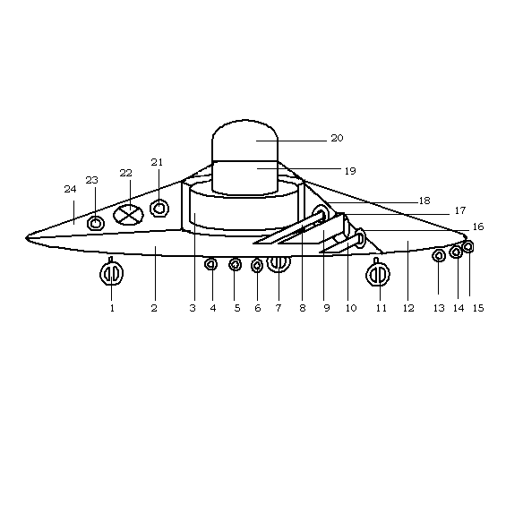
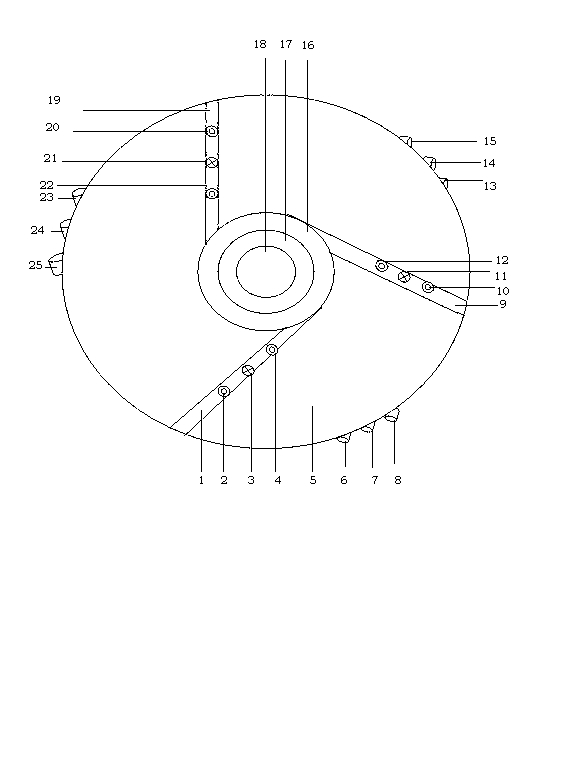
[0015] exist figure 1 In the shown embodiment, the flying saucer spacecraft is shaped like a flying saucer. The fuel tank (3) is installed in the lower part of the center of the flying saucer spacecraft, the control system (19) of the flying saucer spacecraft is installed in the middle, and the launch chamber (satellite warehouse, missile warehouse) is installed in the upper part. , spaceship warehouse) (20); the upper layer of the flying saucer spacecraft is provided with a group A rocket engine air inlet (17), A group No. 1 air duct air inlet (18), A group No. 2 air duct air inlet ( 16), Group C rocket engine inlet (22), Group C No. 1 air duct inlet (21), Group C No. 2 air duct inlet (23); the middle layer of the flying saucer spacecraft is provided with Group A rocket Engine (9), Group A Air Duct No. 1 (8), Group A No. 2 Air Duct (10); Group C Air Duct Air Inlet and Rocket Engine Air Inlet Mounting Bracket (24) for connecting Group C Air Duct and rocket engines. The lower...


PUM


Abstract

The invention provides a flying saucer spacecraft, and relates to the spaceflight, aviation and rocket launching fields. A satellite, a missile and a spaceship are launched through combining rocket and space shuttle technologies and utilizing a flying saucer principle and an aerodynamic principle. The flying saucer spacecraft is composed of a central low-portion fuel tank, a central control system, an upper-portion launch silo (a satellite silo, a missile silo, a space ship silo), a rocket engine air inlet and an air pipeline air inlet which are arranged at the upper layer of the flying saucer spacecraft, a rocket engine air outlet and an air pipeline air outlet which are arranged at the lower layer, a rocket engine and an air pipeline which are arranged at the middle layer, and a first tire, a second tire and a third tire which are arranged at the bottom layer of the flying saucer spacecraft. The flying saucer spacecraft has the advantages of high speed, far range, repeated use, substantial reduction of the space activity cost, and the like, and is suitable for launching satellites, missiles and spaceships.

Description

technical field [0001] The invention provides a flying saucer spacecraft and relates to the fields of aerospace, aviation and rocket launching. Background technique [0002] Rockets are currently one of the vehicles that can make objects reach cosmic speeds, overcome or get rid of the gravity of the earth, and enter space. The speed of the rocket is obtained by the working of the rocket engine. The speed of the rocket is proportional to the jet speed of the engine, and increases with the increase of the mass ratio of the rocket. Even with the best liquid hydrogen and liquid oxygen propellants, the jet speed of the engine can only reach 4.3-4.4 km / s. Therefore, it is impossible for a single-stage rocket to send an object into space orbit, and a multi-stage rocket must be used to send the spacecraft into space orbit in a relay manner. There are several connection modes between the stages of a multi-stage rocket, such as series connection, parallel connection and series-para...

Claims


Application Information

Patent Timeline
Patent Type & Authority Applications(China)
IPC IPC(8): B64C39/06B64D27/16B64D33/00
Inventor 罗才德
Owner 罗才德
Why Eureka
Try Eureka