
WMT solar cell module and preparation method thereof

A technology of solar cells and components, applied in electrical components, circuits, photovoltaic power generation, etc., can solve the problems of MWT components that cannot be popularized and applied, clean energy pollution, high prices, etc., to solve scratches and environmental pollution, and save costs , the effect of improving life expectancy

Inactive Publication Date: 2013-08-21
CECEP SOLAR ENERGY TECH (ZHENJIANG) CO LTD
View PDF4 Cites 11 Cited by
  • Summary
  • Abstract
  • Description
  • Claims
  • Application Information

AI Technical Summary

Problems solved by technology

During the entire assembly process, there are mainly the following shortcomings and deficiencies: 1. Since the positive and negative electrodes of the battery are concentrated on the back of the battery, the metal conductive layer on the conductive foil needs to be isolated and short-circuited. The conductive foil that matches the electrode pattern on the back of the MWT solar cell is mainly separated by chemical corrosion or CNC machine tool cutting. Since the conductive foil is connected to the back plate, it is easy to scratch the back plate during the preparation process. At the same time, the chemical If the corrosion method is not properly controlled, it is easy to corrode the backplane, and it is also a kind of pollution for clean energy
2. The high price of traditional backplane materials leads to high component costs
3. Due to the design problems of the product itself, such MWT components cannot be widely applied in BIPV

Method used


Image

  • WMT solar cell module and preparation method thereof

Examples


Embodiment 1

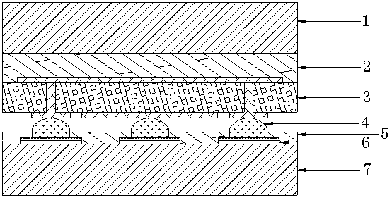
[0021] Embodiment 1: The MWT solar cell assembly of the present invention consists of an upper layer of glass 1, a first hot-melt adhesive film layer 2, a MWT solar cell string 3, a conductive adhesive layer 4, a second hot-melt adhesive film layer 5, and a conductive foil stacked in sequence. The layer 6 and the lower glass 7 are packaged, and the pattern of the conductive foil layer 6 matches the electrode pattern on the back of the MWT solar cell string 3; the second hot-melt adhesive film layer 5 corresponds to the conductive foil layer 6 A hole is opened at the position, so that the conductive foil layer 6 can be in contact with the electrodes on the back of the MWT solar cell string 3; the conductive adhesive layer 4 is arranged on the conductive foil layer 6 and the electrodes on the back of the MWT solar cell string 3 between. The MWT solar battery string 3 is composed of a plurality of MWT solar battery sheets with emitter electrodes and base electrodes printed on the...


PUM


Abstract

The invention discloses a WMT solar cell module. The WMT solar cell module is formed by upper layer glass, a first hot melt adhesive film layer, a MWT solar cell string, a conductive adhesive layer, a second hot melt adhesive film layer, a conductive foil layer and lower layer glass in a sealing mode, wherein the upper layer glass, the first hot melt adhesive film layer, the MWT solar cell string, the conductive adhesive layer, the second hot melt adhesive film layer, the conductive foil layer and the lower layer glass are sequentially stacked. The pattern of the conductive foil layer is matched with the pattern of the electrode at the back side of the MWT solar cell string. A hole is formed in the position, corresponding to the conductive foil layer, of the second hot melt adhesive film layer, and the conductive foil layer is enabled to be capable of being contacted with the electrode at the back side of the MWT solar cell string. The conductive adhesive layer is arranged between the conductive foil layer and the electrode at the back side of the MWT solar cell string. The invention further discloses a preparation method of the MWT solar cell module. A two-layer-glass structure is adopted, and the glass has good functions of being moisture-resisting, ageing-resisting, ultraviolet-resisting, and not prone to be ageing. Compared with a rear panel of conventional molecular materials, the WMT solar cell module is very good in weather resistance, and therefore the service life of the module can be prolonged.

Description

technical field [0001] The invention relates to the technical field of photovoltaic power generation, in particular to a MWT solar cell module and a preparation method thereof. Background technique [0002] Energy and the environment are two major issues that are widely concerned in the world today. As a renewable green energy, solar energy has naturally become a hot spot for people to develop and research. Photovoltaic power generation technology is a main direction of solar energy utilization, and crystalline silicon solar cells occupy the vast majority of the current photovoltaic market. [0003] The photoelectric conversion efficiency of a solar cell has a great relationship with the light-receiving area on the front of the solar cell. Due to the limitation of the front electrode, traditional solar cells inevitably cause a large loss of light-receiving area, resulting in a decrease in photoelectric conversion efficiency. [0004] MWT (Metal Wrap-Through) metal wound ba...

Claims


Application Information

Patent Timeline
Patent Type & Authority Applications(China)
IPC IPC(8): H01L31/048H01L31/18
CPCY02E10/50Y02P70/50
Inventor 杨磊范维涛勾宪芳姜利凯王鹏
Owner CECEP SOLAR ENERGY TECH (ZHENJIANG) CO LTD
Learn More