USB connector

A connector and electrical connection technology, which is applied in the direction of protective grounding/shielding devices of connecting parts, contact parts, etc., can solve the problems of the overall structure of the USB connector, such as the loss of simplicity, the number of welding points, and the increase of virtual welding. Excellent electromagnetic interference effect, convenient manufacturing and assembly, and the effect of reducing the number of parts

Inactive Publication Date: 2013-08-21
CHANGSHU HONGBO COMM TECH CO LTD
View PDF11 Cites 4 Cited by
  • Summary
  • Abstract
  • Description
  • Claims
  • Application Information

AI Technical Summary

Problems solved by technology

[0006] Not limited to the above exemplified patent solutions, there are the following disadvantages: First, due to the large number of parts, not only manufacturing troubles, but also cumbersome assembly affects production efficiency. The grounding shrapnel is grounded between the headers and has a set (the patent indicates three) feed points, so the process of welding the grounding shrapnel to the PCB board is cumbersome and the reliability of the welding is difficult to guarantee. The upper and lower shells are shielded, so the overall structure of the USB connector is not simple, and the volume is increased and the cost is increased; secondly, due to the neglect of the grounding function of the grounding terminal in the terminal mechanism, it leads to welding There are many points, and there is a risk of weak plug-in resistance, because the more solder joints, the probability of virtual soldering and / or missing soldering increases accordingly; The terminal mechanism and the metal shell are reliably grounded, so the suppression of the interference of magnetic waves on the transmission signal is not enough to meet the expectations of the industry

Method used


Image

  • USB connector
  • USB connector

Examples


Embodiment Construction

[0022] In order to enable the examiners of the patent office, especially the public, to understand the technical essence and beneficial effects of the present invention more clearly, the applicant will describe in detail the following in the form of examples, but none of the descriptions to the examples is an explanation of the solutions of the present invention. Any equivalent transformation made according to the concept of the present invention which is merely formal but not substantive shall be regarded as the scope of the technical solution of the present invention.

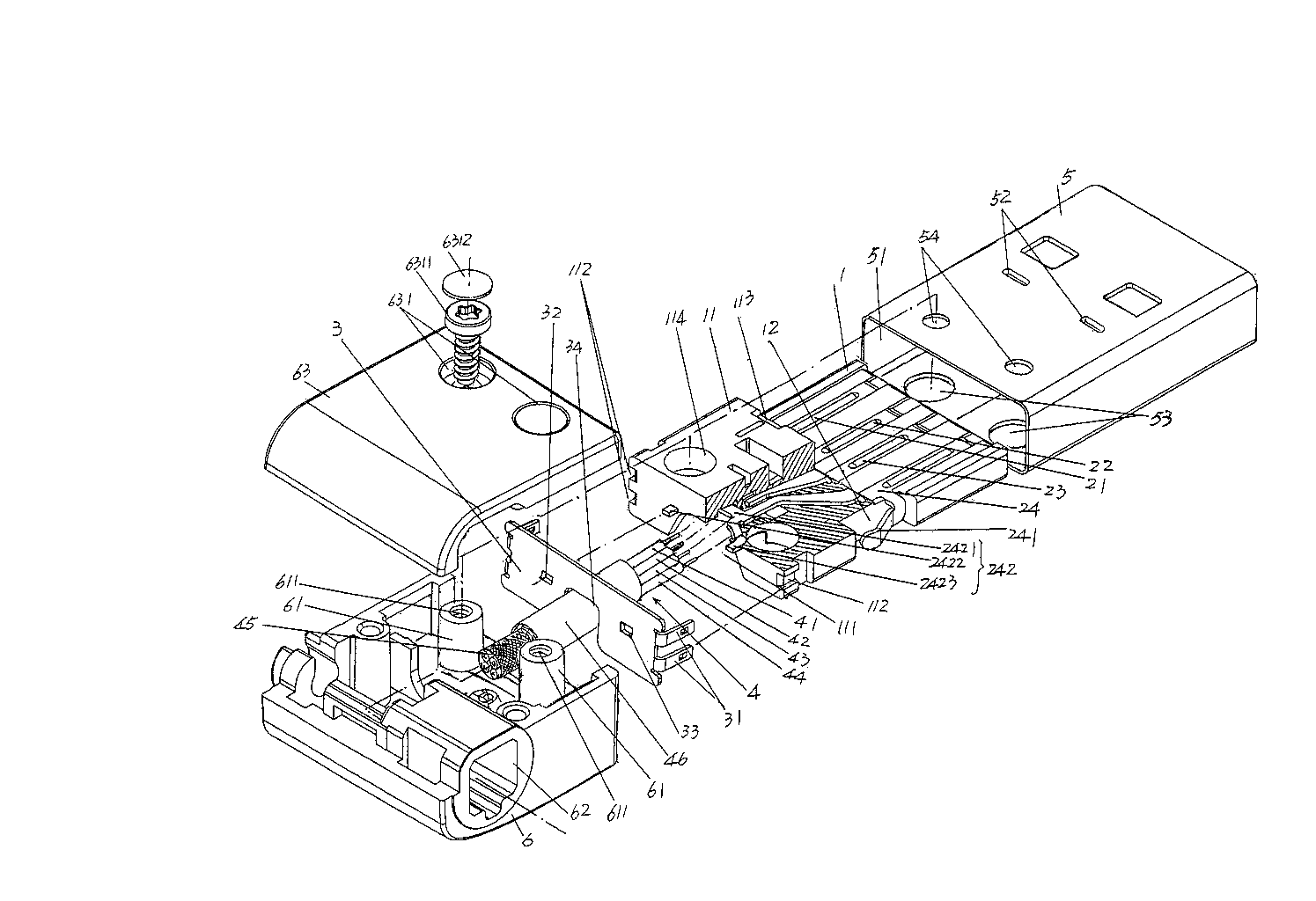
[0023] Please see figure 1 , provides an insulating colloid 1 whose material is preferably plastic and formed by molding, and a tailstock 11 is formed on the insulating colloid 1, more specifically, the tailstock 11 is integrally formed on the insulating colloid 1 facing downward. One end of the described tailstock cover 3, or an end towards the cable 4 described below. currently by figure 1 The position st...


PUM


Abstract

The invention discloses a USB connector, and belongs to the technical field of electric connectors. The USB connector comprises an insulating colloid, a terminal mechanism, a tail seat protective cover, a cable and a metal outer shell. The USB connector is characterized in that a grounded elastic piece demising concave cavity is formed in the lateral wall of one end, facing towards a power source negative pole connecting terminal, of the insulating colloid, a positive voltage data line connecting terminal and a negative voltage data line connecting terminal are located between a power source positive pole connecting terminal and the power source negative pole connecting terminal, a grounded elastic piece is arranged on the power source negative pole connecting end in an extending mode, and the grounded elastic piece stretches into the grounded elastic piece demising concave cavity and is contacted with a cavity wall of a shell cavity of the metal outer shell. The USB connector has the advantages that the number of components is reduced, the connector is convenient to manufacture and assemble, weakening to the contacting effect caused by repeated plugging and pulling during use processes will not occur due to the fact that welding is eliminated, and the effect of resisting electro-magnetic interference is superior.

Description

technical field [0001] The invention belongs to the technical field of electrical connectors, in particular to a USB connector. Background technique [0002] USB (full name in English: Universal Serial Bus, Chinese name: Universal Serial Bus) is an external bus standard used to standardize the connection and communication between computers and external devices, and is an interface used in the PC field. After years of development, USB2.0 has become the preferred interface for high-speed data transmission equipment. It increases the transmission rate from 12Mbps in USB1.1 to 480Mbps, or 60MB / s, which can basically meet the speed requirements of most peripheral devices. [0003] As the transmission rate increases, people's requirements for the quality of the transmission signal also increase accordingly. If the USB connector lacks an effective signal shielding structure, the signal transmission capability will be weakened, and the transmission quality will not be guaranteed. ...

Claims


Application Information

Patent Timeline
Patent Type & Authority Applications(China)
IPC IPC(8): H01R13/02H01R13/24H01R13/652H01R13/658
Inventor 莫如红
Owner CHANGSHU HONGBO COMM TECH CO LTD
Why Eureka
Try Eureka