Scanning device of medical detector and automatic assembling and disassembling device for medical rod source

An automatic loading and unloading and scanning device technology, which is applied in the field of medical machinery, can solve problems such as large operating errors in manual operations, low reliability of rod source installation, and damage to operating technicians, so as to improve efficiency, avoid radiation damage, and improve reliability.

Active Publication Date: 2013-08-28
沈阳智核医疗科技有限公司
View PDF2 Cites 10 Cited by
  • Summary
  • Abstract
  • Description
  • Claims
  • Application Information

AI Technical Summary

Problems solved by technology

[0006] During the above operation process, the operator’s manual operation is completely exposed to the gamma ray radiation of rod source 03, the radiation intensity is generally 2-5mCi, which will cause damage to the operator who has been engaged in PET and CT scanning for a lo

Method used


Image

  • Scanning device of medical detector and automatic assembling and disassembling device for medical rod source
  • Scanning device of medical detector and automatic assembling and disassembling device for medical rod source
  • Scanning device of medical detector and automatic assembling and disassembling device for medical rod source

Examples


Embodiment 1

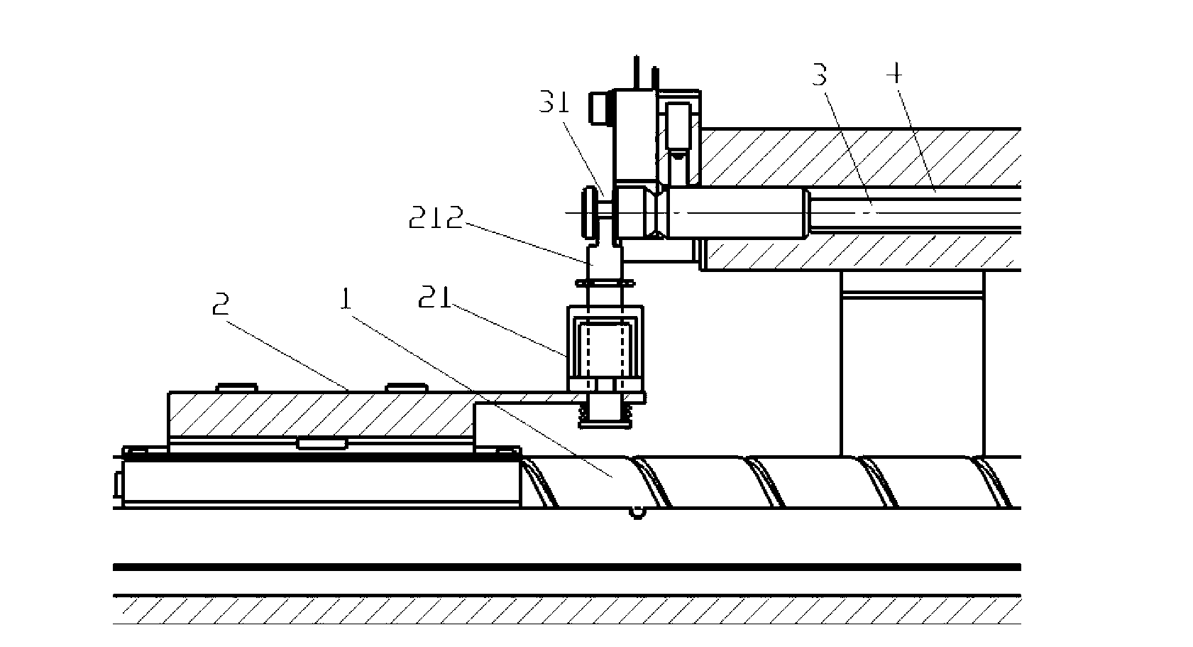
[0047] Please refer further Figure 3-7 , image 3 It is a cross-sectional view of the automatic loading and unloading device provided by the present invention before sending rods in the first embodiment; Figure 4 for image 3 The cross-sectional view of the automatic loading and unloading device shown in the rod feeding process; Figure 5 for image 3 The cross-sectional view of the automatic loading and unloading device shown after the rod feeding is completed; Image 6 for image 3 The cross-sectional view of the automatic loading and unloading device shown after the rod is unloaded; Figure 7 for adoption image 3 The flow chart of the automatic loading and unloading device for feeding and unloading rods is shown.

[0048] In the first embodiment, the electromagnet 21 can be provided with a collet 212 which can be attracted to the electromagnet 21 , and the collet 212 is arranged in cooperation with the tail of the rod source 3 .

[0049] When the electromagnet 21...

Embodiment 2

[0059] Please refer to Figure 8-Figure 11 , Figure 8 It is a cross-sectional view of the automatic loading and unloading device provided by the present invention before sending rods in the second specific embodiment; Figure 9 for Figure 8 The cross-sectional view of the automatic loading and unloading device shown after the rod feeding is completed; Figure 10 for Figure 8 The cross-sectional view of the automatic loading and unloading device shown after the rod is unloaded; Figure 11 for adoption Figure 8 The flow chart of the automatic loading and unloading device for feeding and unloading rods is shown.

[0060] In the second specific embodiment, the tail end of the rod source 3 is a steel structure, and the electromagnet 21 can have a suction part 211, and the suction part 211 can be attracted to the tail end of the rod source 3, thereby fixing the rod source 3 .

[0061] The suction part 211 can be a structure independently arranged on the electromagnet 21, ...


PUM


Abstract

The invention provides a scanning device of a medical detector and an automatic assembling and disassembling device for a medical rod source. By the aid of the scanning device and the automatic assembling and disassembling device, the assembling and disassembling efficiency and precision can be improved, and radiation damage caused by manual operation can be prevented. The automatic assembling and disassembling device comprises a screw which is parallel to the axial direction of the rod source and a nut base which is in threaded connection with the screw, the circumference of the nut base is fixed, and an electromagnet is arranged on the nut base, so that the rod source can be connected or separated through control of energization and deenergization of the electromagnet. When a rod is required to be fed, the electromagnet is energized or deenergized, the rod source is positioned by the electromagnet, then the screw is driven to rotate in a forward direction, and the nut base drives the electromagnet on the nut base and the rod source to move with the nut base along the axial direction of the screw, so that the rod source is pushed to move towards the detector and finally sent into the detector. By the aid of the structure, the automatic assembling and disassembling of the rod source is achieved, the radiation damage caused by manual operation is prevented, the operation precision is high, and the reliability of rod source installation is improved.

Description

technical field [0001] The invention relates to the technical field of medical machinery, in particular to an automatic loading and unloading device for medical rod sources. Background technique [0002] At present, PET (positron emission tomography, positron emission tomography) and CT (computed tomography, motor computer X-ray tomography) technologies are widely used in the field of medical technology. Usually, before the use of PET and CT products, a normalized calibration scan is required to scan the rod source through its rod source to achieve the gain setting of the rod source, so that the rod source can work in the best state and reduce the cost caused by detector manufacturing and assembly. Image artifacts caused by errors can improve the image quality acquired by rod sources. [0003] Please refer to figure 1 , figure 1 It is a schematic diagram of a three-dimensional structure of a rod source inserted into a detector in a specific embodiment in the prior art. ...

Claims


Application Information

Patent Timeline
IPC IPC(8): A61B6/03
Inventor 杨波杜卫刚梁国栋高岩王清田胜辉王云琴赵国涛
Owner 沈阳智核医疗科技有限公司
Why Eureka
Try Eureka