Magnetic internally-circulating fluidized bed adsorber

A technology of internal circulation and adsorber, which is applied in the field of magnetic internal circulation fluidized bed adsorber, can solve the problems of difficult solid-liquid separation in fluidized bed, decrease of specific surface area, decrease of adsorption efficiency, etc., and achieve large solid-liquid contact area, transmission The effect of fast quality and small amount of adsorbent

Inactive Publication Date: 2013-08-28
NANJING UNIV OF SCI & TECH
View PDF5 Cites 5 Cited by
  • Summary
  • Abstract
  • Description
  • Claims
  • Application Information

AI Technical Summary

Problems solved by technology

The fixed bed adsorber has the following disadvantages: (1) Intermittent operation requires backup equipment, that is, when a part of the adsorber is adsorbed, another part of the adsorbent is regenerated; (2) In order to ensure water outlet, the height of the adsorption area must have a certain margin , need to place more adsorbent than the actual; (3) For a thicker bed, the pressure loss is large, and the energy consumption is high; (4) The adsorbent needs to be shaped into particles, so that the specific surface area decreases and the adsorption efficiency decreases
However, for fine particle adsorbents, it is difficult to achieve solid-liquid separation in a fluidized bed, which limits the application of some adsorbents (such as powdered activated carbon) with small particles, large specific surface area, fast adsorption rate, and high capacity. In adsorption, precipitation and other processes, there are often contradictions between the pursuit of high efficiency and solid-liquid separation

Method used


Image

  • Magnetic internally-circulating fluidized bed adsorber
  • Magnetic internally-circulating fluidized bed adsorber
  • Magnetic internally-circulating fluidized bed adsorber

Examples


Embodiment

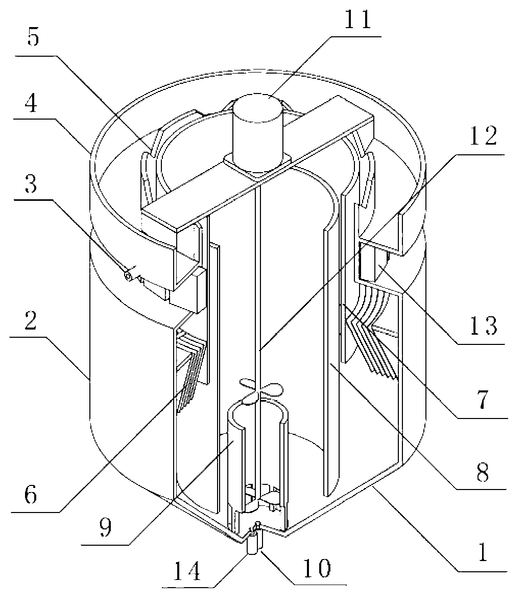
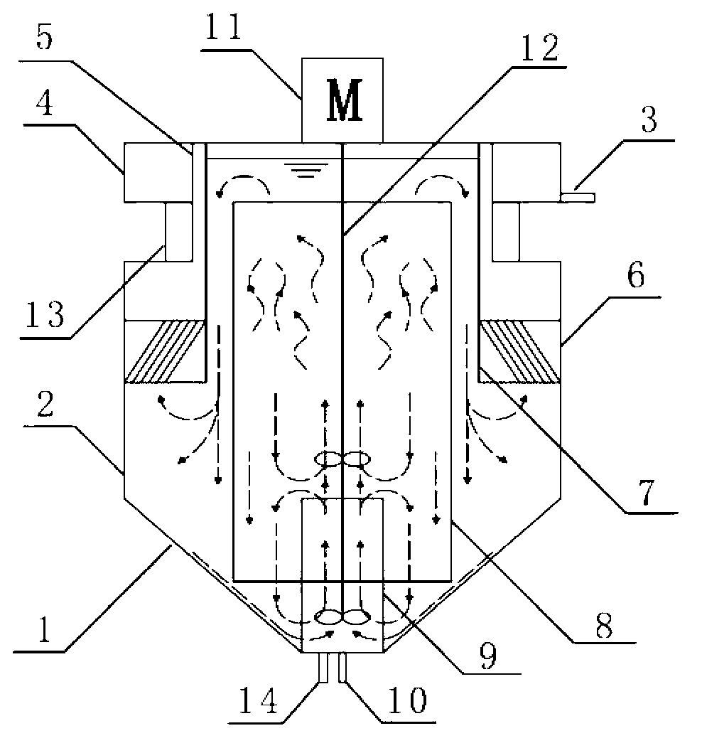
[0022] Such as figure 1 Shown: a magnetic internal circulating fluidized bed adsorber, including a vertebral body 1, a cylinder body 2, an outlet pipe 3, a water collection tank 4, an overflow weir 5, an inclined plate 6, an outer guide cylinder 7, and an intermediate cylinder body 8 , inner guide tube 9, water inlet pipe 10, motor 11, stirring paddle 12, magnet 13 and adsorbent discharge pipe 14; On the side of the water inlet pipe 10 at the bottom, the upper edge of the inner guide tube 9 is on the same level as the upper edge of the cone 1, the upper edge of the middle cylinder 8 is on the same level as the bottom of the sump 4, and the inner guide tube 9 is on the same level as the cone 1. Fixed connection, the middle cylinder body 8, the outer guide tube 7 and the inclined plate 6 are fixedly connected with the cylinder body 2, the lower edge of the middle cylinder body 8 is lower than the upper edge of the inner guide tube 9; the lower end of the inner guide tube 9 is ci...


PUM


Abstract

The invention discloses a magnetic internally-circulating fluidized bed adsorber; a water inlet pipe is arranged in the center of the bottom of a cone; an adsorbent discharge pipe is arranged at one side of the water inlet pipe at the bottom of the cone; the upper edge of an inner guide cylinder and the upper edge of the cone are arranged on the same plane; the upper edge of a middle cylinder body and the bottom of a water collection tank are arranged on the same plane; the inner guide cylinder is fixedly connected with the cone; the middle cylinder body, an outer guide cylinder and an inclined plate are fixedly connected with a cylinder body; a piece of magnet is arranged in a ring groove embedded in the cylinder body; an overflow weir is arranged at the upper edge of the inner side of the water collection groove; a water outlet pipe is arranged at the periphery of the water collection groove and is parallel to the water level; a motor is arranged just above the magnetic internally-circulating fluidized bed adsorber by a bracket; a stirring paddle is connected with the motor by a coupler; and the stirring paddle is arranged on the center line of the magnetic internally-circulating fluidized bed adsorber. The magnetic internally-circulating fluidized bed adsorber is convenient to operate, little in adsorbent consumption, low in energy consumption and high in adsorption efficiency.

Description

technical field [0001] The invention belongs to the field of sewage adsorption treatment, in particular to a magnetic internal circulating fluidized bed adsorber. Background technique [0002] The heavy metals and refractory organic substances contained in many industrial wastewaters are difficult or impossible to remove by conventional biological methods, and these substances can be removed by adsorption methods. [0003] The commonly used adsorption equipment for wastewater treatment by adsorption method includes fixed bed and fluidized bed. At present, most of the adsorbents used for water treatment are granular, such as activated carbon, sulfonated coal, etc., and the adsorbers used are traditional fixed-bed adsorbers. The fixed bed adsorber is to fix the adsorbent on a certain part and carry out the adsorption operation when it is still. Most of them are cylindrical equipment. Pollutants in the adsorbent are adsorbed on the adsorbent. The fixed bed adsorber has the f...

Claims


Application Information

Patent Timeline
Patent Type & Authority Applications(China)
IPC IPC(8): C02F1/28C02F1/48
Inventor 江芳汪信张磊陈欢
Owner NANJING UNIV OF SCI & TECH
Why Eureka
Try Eureka