Eureka AIR delivers breakthrough ideas for toughest innovation challenges, trusted by R&D personnel around the world.

Thermal-insulation guide support for large-caliber directly-buried tube

A technology for guiding brackets and pipes, applied in the directions of pipeline brackets, pipeline protection through thermal insulation, pipeline protection, etc., can solve the problems of inconvenient installation of thermal insulation layers, large friction and noise, easy aging, falling off, etc., and achieve tight bonding , reduce vibration, create simple effects

Inactive Publication Date: 2013-08-28
JIANGSU MINGJIANG MACHINERY MFG
View PDF5 Cites 5 Cited by
  • Summary
  • Abstract
  • Description
  • Claims
  • Application Information

AI Technical Summary

Problems solved by technology

[0003] Existing heat-insulating guide brackets for direct buried pipes ≥ DN600 often use high-temperature-resistant asbestos mats as the heat-insulating layer, which requires multiple layers of winding outside the core pipe to meet the heat preservation requirements. The temperature resistance is relatively low, usually only about 200°C, and It is easy to age and fall off, and the installation of the heat insulation layer is inconvenient, time-consuming and laborious; thermal bridges are prone to occur between the heat insulation bracket and the core tube, resulting in a large amount of heat loss and energy waste; in addition, the bottom of the heat insulation bracket and the outer tube Where the walls are in contact, polytetrafluoroethylene sliders are often padded to reduce the friction coefficient, because it is surface contact sliding, and the friction and noise are relatively large

Method used


Image

  • Thermal-insulation guide support for large-caliber directly-buried tube
  • Thermal-insulation guide support for large-caliber directly-buried tube

Examples


Embodiment Construction

[0013] The present invention will be further described below in conjunction with specific drawings.

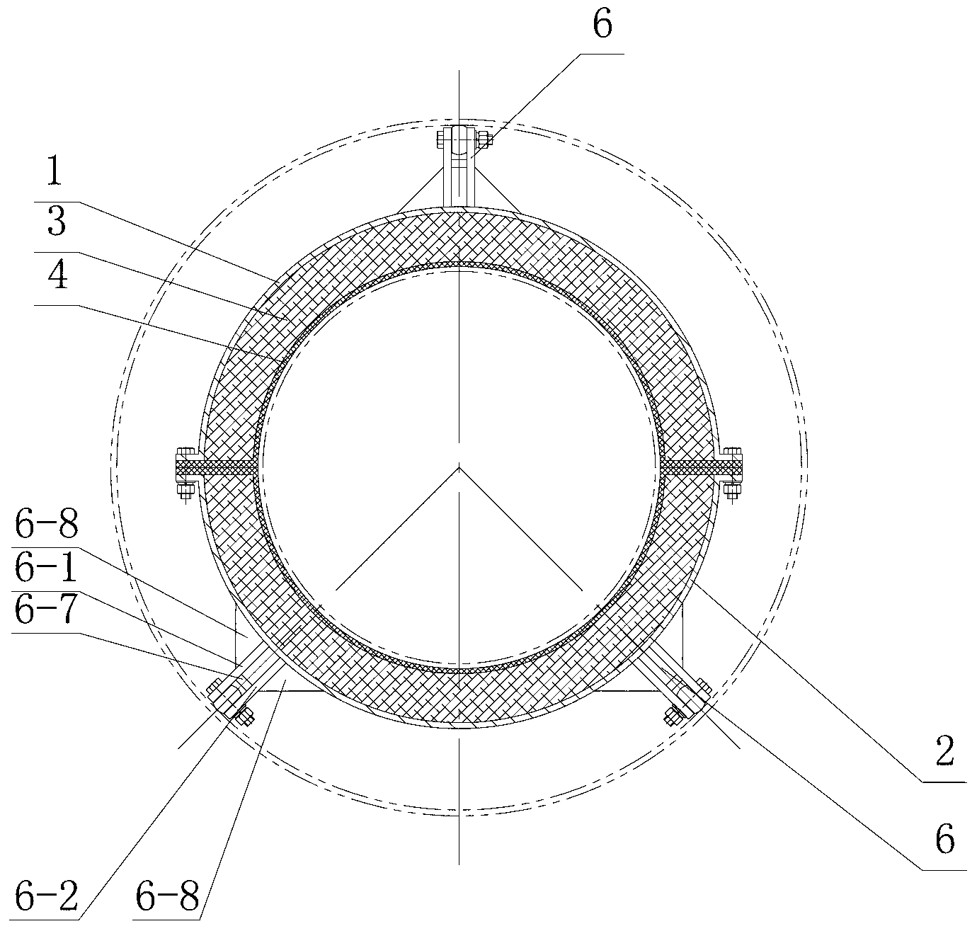
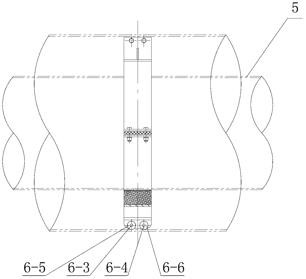
[0014] like figure 1 , figure 2 As shown: the heat insulation guide bracket for large-diameter direct buried pipe includes upper pipe clamp 1, lower pipe clamp 2, hard heat insulation layer 3, soft heat insulation layer 4, core pipe 5, double roller structure 6, first support Plate 6-1, second support plate 6-2, first roller shaft 6-3, second roller shaft 6-4, first roller 6-5, second roller 6-6, shin plate 6-7, rib Plates 6-8 etc.

[0015] The present invention includes a pipe clip body, which is formed by connecting an upper pipe clip 1 and a lower pipe clip 2; the upper pipe clip 1 and the lower pipe clip 2 are semicircular, and the upper pipe clip 1 and the lower pipe clip 2 are connected to form a ring structure; the inner arc surfaces of the upper pipe clamp 1 and the lower pipe clamp 2 are provided with a hard heat insulation layer 3, and one side of the hard heat i...


PUM


Abstract

The invention relates to a thermal-insulation guide support for a large-caliber directly-buried tube. The support comprises a tube clamp body, wherein the tube clamp body is formed by an upper tube clamp and a lower tube clamp in a connecting mode. The support is characterized in that the upper tube clamp and the lower tube clamp are both of a semi-circular shape, the upper tube clamp is connected with the lower tube clamp to form an annular structure, the inner cambered surface of the upper tube clamp and the inner cambered surface of the lower tube clamp are both provided with hard thermal-insulation layers, one face of one hard thermal-insulation layer is connected with the inner cambered surface of the upper tube clamp, one face of the other hard thermal-insulation layer is connected with the inner cambered surface of the lower tube clamp, the other face of each hard thermal-insulation layer is provided with a soft thermal-insulation layer, the soft thermal-insulation layers are contacted with core tubes, and the outer cambered surface of the tube clamp body is equally divided into three groups of double idler wheel structures of the same structure. The thermal-insulation guide support can isolate a thermal bridge, improves transmission efficiency, reduces vibration between the tube clamps and the core tubes, and is convenient to install, uniform and stable in stress, smooth in sliding and suitable for being used for the large-caliber directly-buried tube.

Description

technical field [0001] The invention relates to a heat-insulating guide bracket for direct-buried pipes with a large diameter, in particular to a heat-insulated guide bracket for direct-buried pipes with a diameter of ≥ DN600. Background technique [0002] At present, direct-buried steam pipes are usually used for the transmission of steam heat sources. The flow of high-temperature steam in the pipes will cause axial and radial displacements of the steam pipes. Therefore, in long-distance pipes, heat-insulating brackets are required to support the pipes. Three types of brackets are usually used in "steel-steel" direct buried steam pipelines, which are guide brackets, sliding brackets and fixed brackets. Guide brackets are usually used in straight pipe sections with direction changing parts such as elbows and knuckles. It is used to limit the moving space of the working steel pipe in the steel pipe of the outer protective layer, prevent the radial displacement of the core pip...

Claims


Application Information

Patent Timeline
IPC IPC(8): F16L3/10F16L59/135F16L59/15
Inventor 周致中
Owner JIANGSU MINGJIANG MACHINERY MFG
Why Eureka
Eureka Blog
Learn More