Supercharge Your Innovation With Domain-Expert AI Agents!

Burner for a glass melting furnace comprising cooling

A glass melting furnace and burner technology, applied in the direction of burners, glass furnace equipment, gas fuel burners, etc., can solve problems such as cracking and injector blockage

Active Publication Date: 2013-08-28
AGC GLASS EUROPE
View PDF5 Cites 2 Cited by
  • Summary
  • Abstract
  • Description
  • Claims
  • Application Information

AI Technical Summary

Problems solved by technology

Above a temperature of about 150°C, it may suffer from cracking, which can lead, inter alia, to clogging of injectors

Method used


Image

  • Burner for a glass melting furnace comprising cooling
  • Burner for a glass melting furnace comprising cooling
  • Burner for a glass melting furnace comprising cooling

Examples


Embodiment Construction

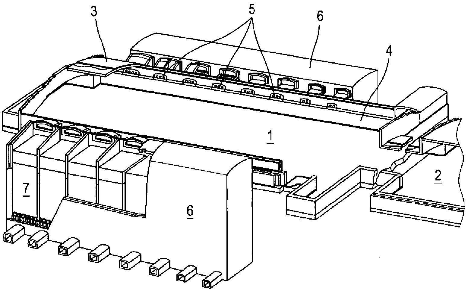
[0035] figure 1 The kiln shown consists of the following main parts: A tank 1 made of refractory material, in which the raw material is injected at the left end. Appears as an empty pool that fills with molten glass at runtime. Glass flows from left to right and communicates with refining tank 2 .

[0036] The pool belongs to a closed whole, the upper part forms the furnace roof, of which only a small part is shown 3 . The side wall body 4 has an opening 5 which communicates with a regenerator lined with refractory material 7 .

[0037] The kiln is constructed in a symmetrical manner with respect to its longitudinal axis. The opening of the wall faces the same opening of the other wall, and each opening communicates with a regenerator.

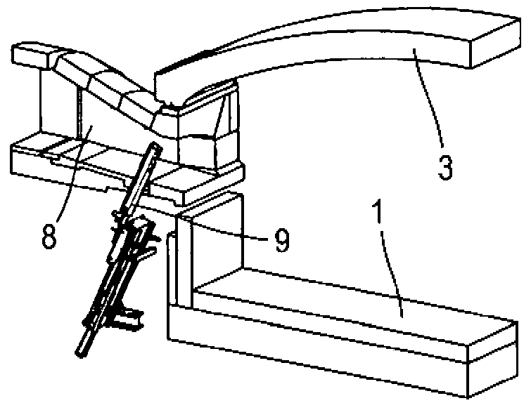
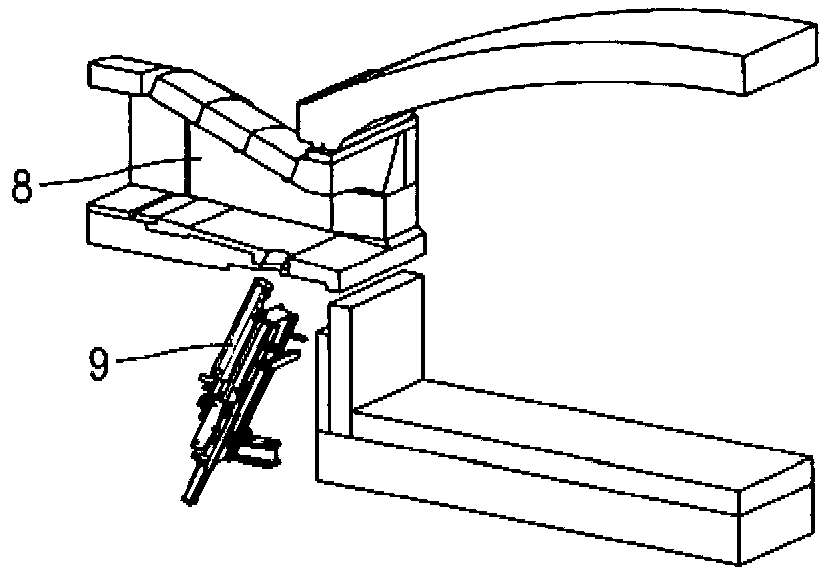
[0038] exist figure 2 with image 3 In the preferred mode according to the invention shown, the burner 9 is arranged in the inlet pipe 8 connecting the regenerator with the opening 5 .

[0039] image 3 The burner 9 is shown in the ac...


PUM


Abstract

The present invention relates to a burner for a glass melting furnace, including a liquid fuel supply and a gaseous fuel supply in a single assembly, both supplies being able to operate separately or simultaneously, wherein the temperature of the burner is controlled by circulating coolant within the burner.

Description

technical field [0001] The present invention relates to glass melting furnaces in which raw materials are injected into a glass melting pool furnace, the temperature in which the raw materials are melted in the furnace is guaranteed by radiant heat transfer by means of flames generated by burners. Background technique [0002] In large glass melting furnaces, the traditional setup consists in feeding raw materials into one end of a long furnace and retrieving molten and refined glass at the other end. To ensure melting followed by refining, burners are placed along the pool, distributing the energy required for the different stages of progress in the kiln. Upstream requires maximum energy to allow the raw material to melt, the refinery just needs to maintain the right temperature. [0003] Melting furnaces are usually large capacity for economical reasons. Production can reach values ​​of about 1000 tons of glass per day. Such quantities require a large energy supply, whi...

Claims


Application Information

Patent Timeline
IPC IPC(8): C03B5/235F23D17/00
CPCC03B5/235C03B5/2353F23C2900/07021F23D11/38F23D14/20F23D14/58F23D14/78F23D17/002F23D2900/00006F23L7/007Y02E20/34Y02P40/50
Inventor G·比里斯A·孔蒂诺C·德森凡斯C·图恩
Owner AGC GLASS EUROPE
Features
  • R&D
  • Intellectual Property
  • Life Sciences
  • Materials
  • Tech Scout
  • Unparalleled Data Quality
  • Higher Quality Content
  • 60% Fewer Hallucinations
Learn More