Visual tracking monitoring system and method in automatic corrugated thin plate fillet weld welding

An automatic welding and corrugated thin plate technology, which is applied in welding equipment, arc welding equipment, manufacturing tools, etc., can solve the problems of fast welding speed, large assembly gap change, uncertain assembly gap offset, etc., to improve welding quality and efficiency , good welding quality and good adaptability

Active Publication Date: 2013-09-04
SOUTH CHINA UNIV OF TECH
View PDF7 Cites 53 Cited by
  • Summary
  • Abstract
  • Description
  • Claims
  • Application Information

AI Technical Summary

Problems solved by technology

The problem with this method is that the dynamic light intensity of the arc light in this area is extremely strong, and it is difficult for general industrial cameras to directly image this area. In addition, because the field of view is limited to the welding area, the trajectory of the welding seam cannot be predicted, so the path of the welding torch cannot be planned
[0005] The monitoring and tracking of corrugated plate fillet welds, especially container side plate fillet welds, has always been a difficult problem for enterprises to apply automatic welding equipment. The workpiece to be welded is...

Method used


Image

  • Visual tracking monitoring system and method in automatic corrugated thin plate fillet weld welding
  • Visual tracking monitoring system and method in automatic corrugated thin plate fillet weld welding
  • Visual tracking monitoring system and method in automatic corrugated thin plate fillet weld welding

Examples


Embodiment

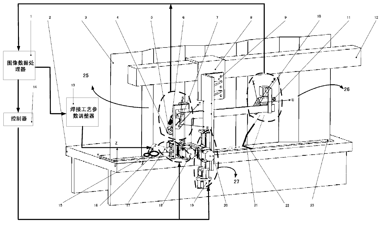
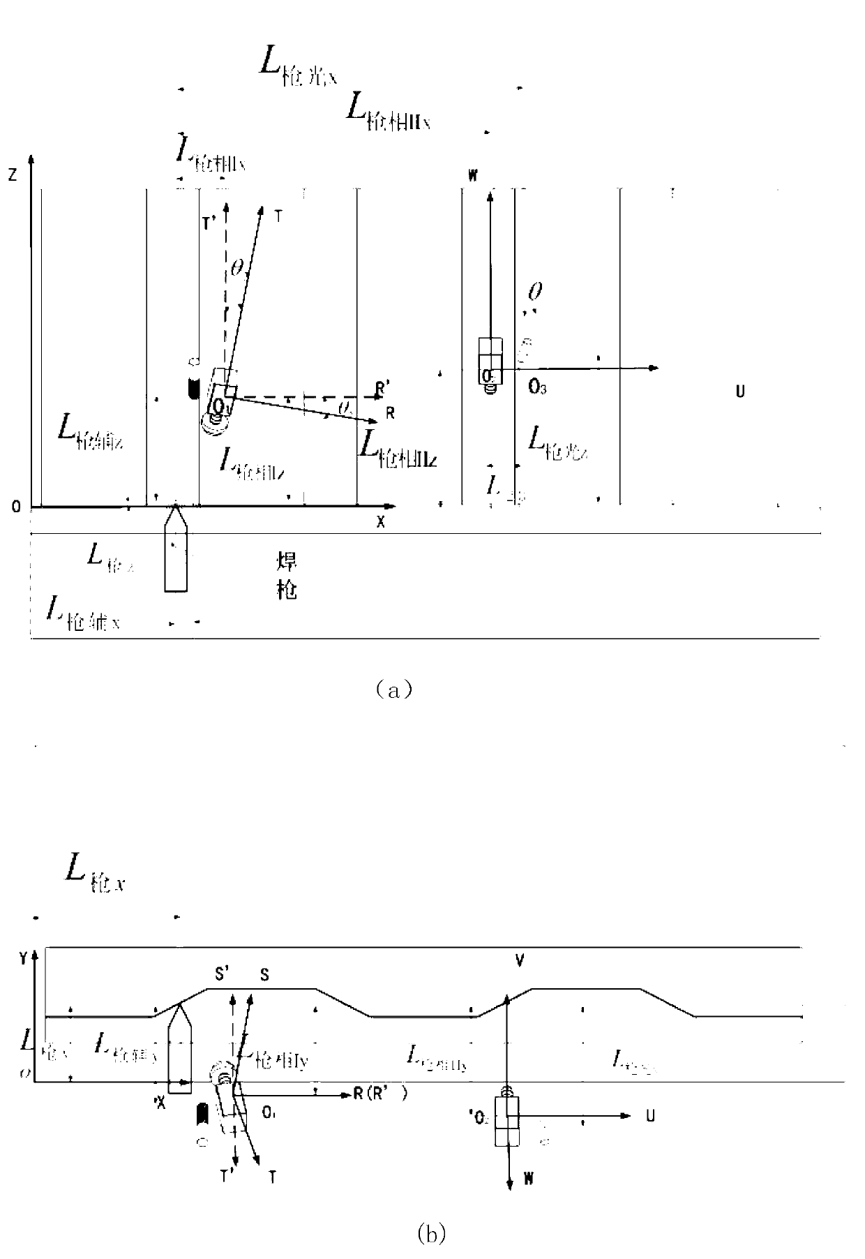
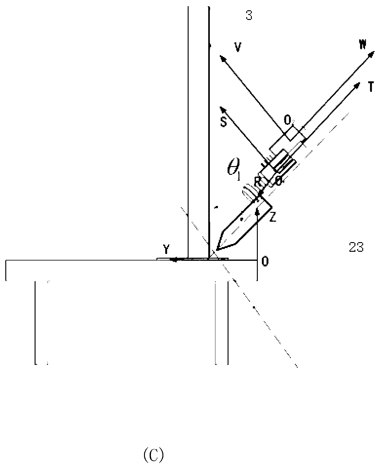
[0054] In this embodiment, the working coordinate system XYZ of the welding torch takes the length direction of the welding workbench 2 as the X direction, the direction perpendicular to the plane of the welding workbench as the Z direction, the direction perpendicular to the surface XZ as the Y direction, and the origin as the lower left corner of the welding workbench Vertex, the welding torch moves from left to right, the XOY plane coincides with the theoretical surface of the base plate to be welded 23, industrial camera I coordinate system RST, origin O 1 , the coordinate system of the industrial camera II10 is UVW, the origin O 2 , the above three coordinate systems can be converted to each other.

[0055] Such as figure 1 As shown, a visual tracking and monitoring system in the automatic welding of corrugated sheet fillet welds includes a welding torch 17, a system mounting frame 9, a welding process parameter adjuster 14, a visual device I25, a visual device II26, and...


PUM


Abstract

The invention discloses a visual tracking monitoring system and method in automatic corrugated thin plate fillet weld welding. The visual tracking monitoring system and method in the automatic corrugated thin plate fillet weld welding comprises a welding gun, a system installing frame, a welding technological parameter adjuster, a vision device I, a vision device II, an image data processor, a welding gun drive device, a tracking drive device and a controller. The vision device I and the vision device II are respectively connected with the image data processor; the image data processor is respectively connected with the controller and the welding technological parameter adjuster; the controller is respectively connected with the welding gun drive device and the tracking drive device. According to the visual tracking monitoring system and method in the automatic corrugated thin plate fillet weld welding, binocular vision devices are adopted, the front vision device II is used for leading the movement of the welding gun, the direct-sight vision device I monitors a weld pool and welding joints before the weld pool and conducts adjustment on welding gun track deviation caused by factors such as thermal welding deformation and welding wire bending.

Description

technical field [0001] The invention relates to welding of side wall corrugated plates, in particular to a visual tracking and monitoring system and method for automatic welding of corrugated sheet fillet welds. Background technique [0002] In actual welding production, due to irregular errors in blanking processing and assembly of workpieces to be welded, problems such as thermal deformation of workpieces, welding wire bending, welding arc blowing, and welding mechanism movement deviations may occur during the welding process, which may lead to The width of the seam to be welded is different and causes the welding torch to deviate from the center of the seam to be welded. Therefore, the ideal automatic welding process should automatically track and monitor the trajectory of the seam to be welded and the width of the seam. Based on this, the trajectory of the welding torch and the welding process parameters can be dynamically and timely adjusted. [0003] At home and abroad...

Claims


Application Information

Patent Timeline
IPC IPC(8): B23K9/095B23K9/127B23K9/032
Inventor 全燕鸣毕齐林
Owner SOUTH CHINA UNIV OF TECH
Why Eureka
Try Eureka