Method for plugging diversion tunnel by cast-in-situ reinforced concrete without cutoff by gate and plugging reinforcing cage

A technology of reinforced concrete seal and reinforced cage, which is applied in water conservancy projects, hydroelectric power stations, hydroelectric power generation, etc., can solve the problems of insufficiency, poor quality of diversion tunnel gate piers, catastrophic and other problems, and achieves cost saving, construction Convenience and high quality construction

Active Publication Date: 2013-09-04
中国葛洲坝集团建设工程有限公司
View PDF7 Cites 10 Cited by
  • Summary
  • Abstract
  • Description
  • Claims
  • Application Information

AI Technical Summary

Problems solved by technology

[0025] During the construction of the civil engineering of the lower gate, it was found that the concrete quality of the original diversion tunnel gate pier was very poor, with cavities and vibration leakage. The strength of the concrete was only 10-15Mpa after the rebound test, far less than the design 20Mpa, which could not meet the requirements The pressure of water on the gate and gate pier concrete after the gate is lowered
[0026] The traditional construction method is to lower the gate to block the water first, and let the workers enter the diversion tunnel from the downstream diversion hole to construct the plugging concrete. Because the concrete strength of the gate pier is not strong enough, after the gate is closed, the rapidly rising water level will affect the gate and gate. The pier concrete generates great pressure, and it is likely that the gate will be suddenly damaged by water pressure during the construction of concrete sealing in the diversion tunnel, resulting in catastrophic consequences. For the construction step of retaining water, the construction method of blocking the diversion tunnel with cast-in-place reinforced concrete without gate interruption is adopted.

Method used


Image

  • Method for plugging diversion tunnel by cast-in-situ reinforced concrete without cutoff by gate and plugging reinforcing cage
  • Method for plugging diversion tunnel by cast-in-situ reinforced concrete without cutoff by gate and plugging reinforcing cage
  • Method for plugging diversion tunnel by cast-in-situ reinforced concrete without cutoff by gate and plugging reinforcing cage

Examples


Embodiment Construction

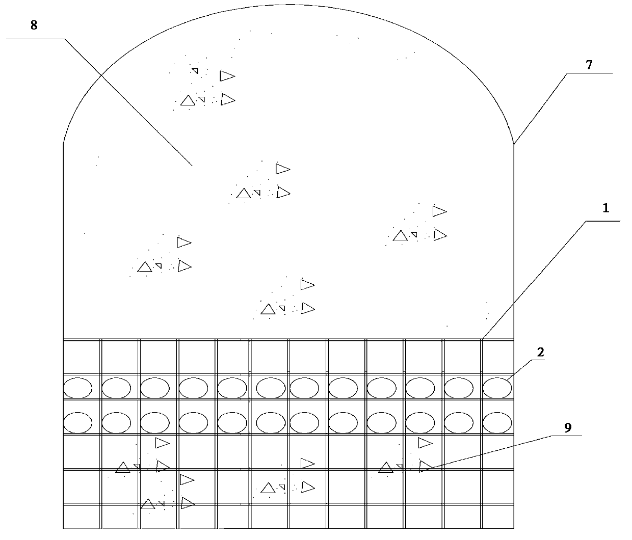
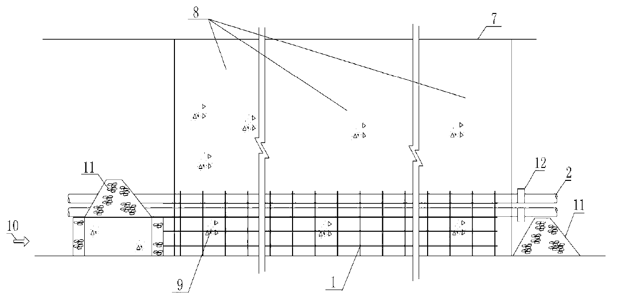
[0055] like figure 1 , figure 2 As shown, a method of plugging diversion tunnels with cast-in-place reinforced concrete without gate cut-off includes the following steps:

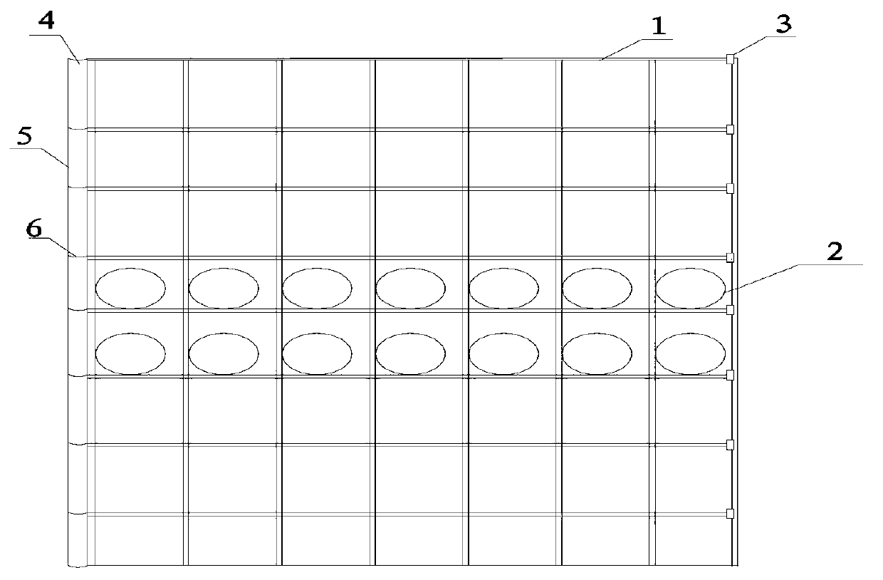
[0056] 1) Make two reinforcement cages on the shore, the longitudinal reinforcement length of the reinforcement cages of the two reinforcement cages is 9m (1.2 times of the height of the diversion tunnel 7.5m), and the length of the transverse reinforcement is 2.5m of the diversion tunnel width (the width of the diversion tunnel 1 / 2 of 5m), the height is 3m, which is 1.5 times of the water flow height of the diversion tunnel in the same period, and N / 2 (the specific steps for N below) are inserted into the two steel cages to make it. Block the reinforcement cage, the two ends of the drainage pipe are 1m longer than the reinforcement cage skeleton, and a gate valve is installed at one end of the drainage pipe. Number the plugged reinforcement cages in turn from side to right, and the numbering sequence is...


PUM


Abstract

The invention discloses a method for plugging a diversion tunnel by cast-in-situ reinforced concrete without cutoff by a gate and a plugging reinforcing cage. The method for plugging the diversion tunnel by the case-in-situ reinforced concrete without cutoff by the gate and the plugging reinforcing cage have the advantages that the process of closing the gate for the diversion tunnel can be removed, the project amount of gate concrete is reduced, and meanwhile concrete plugging can be conducted in the process that normal stream diversion is achieved in the diversion tunnel. The plugging reinforcing cage is fixedly provided with a plurality of drain pipes, after a plurality of plugging reinforcing cages are assembled and combined, a cross sectional area is just the cross sectional area of the diversion tunnel, the plugging reinforcing cages are sequentially placed inside the diversion tunnel, or the diversion tunnel is divided into a plurality of areas to be respectively provided with mesh reinforcing frames with drain pipes in an erecting mode, concrete is sequentially poured, when the concrete strength reaches a design requirement, a gate of the drain pipes is closed, normal pouring is conducted to plug concrete on the back face of the gate, and the gate is poured in the concrete.

Description

technical field [0001] The invention relates to a new technology for diversion tunnel sealing in hydropower stations, in particular to a diversion tunnel sealing technology that does not require gates and gate pier concrete. Background technique [0002] The main building of Chongqing Meixi River Dukouba Hydropower Project is a concrete double-curvature arch dam diversion tunnel, with a maximum dam height of 108.5m. The diversion tunnel is arranged on the left bank of the upstream cofferdam of the arch dam. 483.33m, the elevation of the cave roof is 491.33m (at the entrance of the diversion tunnel), and the size of the cave is 5m×7.5m. The concrete pouring of the dam has been completed and the water retaining conditions are met. The diversion bottom hole on the dam section has also been sealed. It is planned to start the construction of the plugging concrete in November and complete it in December. The average flow rates in November and December are respectively 9.53m 3 / s...

Claims


Application Information

Patent Timeline
Patent Type & Authority Applications(China)
IPC IPC(8): E02B9/02
CPCY02E10/20
Inventor 孙合心林本华李奇李汉涛邸书茵
Owner 中国葛洲坝集团建设工程有限公司
Why Eureka
Try Eureka