Probe rotary type ultrasonic flaw detection device

A flaw detection device, ultrasonic technology, applied in the field of detection, can solve the problems of high processing precision, affecting the signal-to-noise ratio of flaw detection, waveform distortion, etc., and achieve the effect of improving the signal-to-noise ratio of flaw detection and increasing the rotation speed of the probe

Inactive Publication Date: 2013-09-04
陈利光
View PDF4 Cites 14 Cited by
  • Summary
  • Abstract
  • Description
  • Claims
  • Application Information

AI Technical Summary

Problems solved by technology

[0005] The brush coupling method is a contact connection. The brush and slip ring are easy to wear and tear, which will lead to poor contact and often cause many interference signals. At the same time, the brush will also vibrate when sliding at high speed, resulting in poor contact. The working speed of the brush method
Capacitive coupling solves the defect of contact connection, but the instrument and the probe are directly connected in series with a capacitor, which is realized by a large-area copper sheet and has a large parasitic inductance, which will cause the attenuation and occurrence of transmitted pulse signals and echo signals Waveform distortion affects the signal-to-noise ratio of flaw detection
Secondly, the introduction of large capacitors is easily interfered by signals such as motors / inverters in an industrial environment, and it is difficult to debug on site
Finally, rotating capacitors have high requirements on machining accuracy. High-speed rotating stages are prone to deformation due to changes in temperature and other environments. Contact with stationary stages will cause capacitor failure and affect capacitor life. Maintenance after failure requires disassembly of the host head, making installation difficult. , high maintenance cost

Method used


Image

  • Probe rotary type ultrasonic flaw detection device

Examples


Embodiment Construction

[0033] The following will clearly and completely describe the technical solutions in the embodiments of the present invention with reference to the accompanying drawings in the embodiments of the present invention. Obviously, the described embodiments are only some, not all, embodiments of the present invention. Based on the embodiments of the present invention, all other embodiments obtained by persons of ordinary skill in the art without creative efforts fall within the protection scope of the present invention.

[0034] It should be noted that, in the case of no conflict, the embodiments of the present invention and the features in the embodiments can be combined with each other.
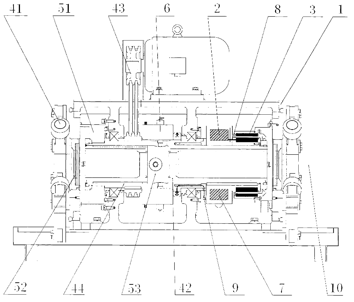
[0035] The basic idea of ​​the present invention is to design a probe rotary ultrasonic flaw detection device, which modularly embeds an ultrasonic flaw detector in an ultrasonic rotary head 1 to form an ultrasonic flaw detection module 2 . Make them rotate together, remove the relative motion be...


PUM


Abstract

The invention provides a probe rotary type ultrasonic flaw detection device. An ultrasonic flaw detector is embedded into an ultrasonic rotary machine head in a modularized manner to form an ultrasonic flaw detection module. The ultrasonic flaw detector and the ultrasonic rotary machine head rotate together to remove relative movement between the ultrasonic flaw detector and the ultrasonic rotary machine head; and the ultrasonic flaw detector and the ultrasonic rotary machine head are fixedly connected by a coaxial cable. The ultrasonic flaw detection module can carry out digital processing and compression on a flaw detection signal and then the flaw detection signal is transmitted to a fixed transmitter in a wireless manner; and then the flaw detection signal is uploaded to a computer by the fixed transmitter to be subjected to treatment and waveform display. According to the probe rotary type ultrasonic flaw detection device disclosed by the invention, the contact problem of electric brush coupling and signal attenuation and anti-interference problems of capacitance coupling in a traditional probe rotary type ultrasonic flaw detection device are solved, the signal to noise ratio of flaw detection is improved and the rotary speed of a probe can also be improved.

Description

technical field [0001] The invention relates to the field of detection, in particular to the field of non-destructive detection technology and equipment for metal and non-metal pipes and rods, in particular to a probe rotating ultrasonic flaw detection device. Background technique [0002] At present, the equipment that uses ultrasonic waves to detect flaws in pipes and rods is mainly divided into two categories: one is that the pipe is advanced in a spiral manner while the ultrasonic probe is still; the other is that the ultrasonic probe is rotated while the pipe is advancing in a straight line. [0003] The first type of equipment, pipe spiral advance, is usually used for low-speed pipe flaw detection because it is difficult to achieve stable high-speed rotation mechanically. The second type of equipment can achieve high speed when the probe rotates, and the straight line of the pipe can realize high-speed flaw detection. [0004] In the traditional probe rotating ultraso...

Claims


Application Information

Patent Timeline
Patent Type & Authority Applications(China)
IPC IPC(8): G01N29/04G08C17/02
Inventor 陈利光刘长华金洲浪虞伟建
Owner 陈利光
Why Eureka
Try Eureka