
Optical module applied in wide temperature range and its working temperature adjustment method

A technology of working temperature and optical modules, applied in lasers, optical fiber transmission, semiconductor lasers, etc., can solve problems such as heat dissipation difficulties, power consumption, device failure, etc., and achieve the effect of saving and compensating power consumption

Active Publication Date: 2016-09-07
HISENSE BROADBAND MULTIMEDIA TECH
View PDF3 Cites 0 Cited by
  • Summary
  • Abstract
  • Description
  • Claims
  • Application Information

AI Technical Summary

Problems solved by technology

[0011] However, in practical application, the inventors of the present invention found that when compensating BIAS current or MOD voltage, certain power consumption will still be consumed; especially in high temperature environment, in order to compensate BIAS current, it is necessary to increase BIAS Current, which increases power consumption due to BIAS compensation current in high temperature environment, resulting in high heat generation and difficulty in heat dissipation of the optical module housing, and the phenomenon of device failure due to excessive temperature

Method used


Image

  • Optical module applied in wide temperature range and its working temperature adjustment method
  • Optical module applied in wide temperature range and its working temperature adjustment method
  • Optical module applied in wide temperature range and its working temperature adjustment method

Examples


Embodiment Construction

[0047] In order to make the object, technical solution and advantages of the present invention clearer, the present invention will be described in further detail below with reference to the accompanying drawings and preferred embodiments. However, it should be noted that many of the details listed in the specification are only for readers to have a thorough understanding of one or more aspects of the present invention, and these aspects of the present invention can be implemented even without these specific details.

[0048] As used herein, terms such as "module" and "system" are intended to include computer-related entities such as, but not limited to, hardware, firmware, a combination of hardware and software, software, or software in execution. For example, a module may be, but is not limited to being limited to being, a process running on a processor, a processor, an object, an executable, a thread of execution, a program, and / or a computer.

[0049] The inventors of the p...


PUM


Abstract

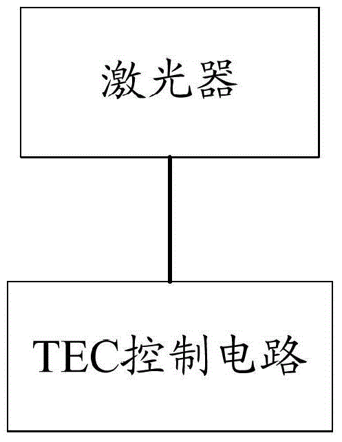
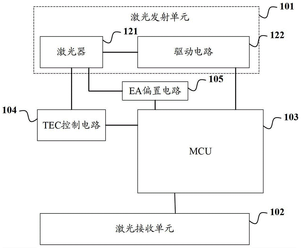
The invention discloses an optical module for a wide temperature range and a working temperature adjusting method thereof. The optical module comprises a laser transmitting unit, an MCU (microprogrammed control unit) and a TEC (total electron content) control circuit, wherein the laser transmitting unit comprises a laser and a drive circuit; the optical power of the laser is previously calibrated to the specific optical power range; the MCU is used for determining the working temperature setting value corresponding to the acquired temperature value after acquiring the temperature value detected by a temperature sensor; and the TEC control circuit is controlled to adjust the working temperature of the laser at the corresponding temperature according to the determined working temperature setting value. Since the working temperature of the laser is allowed to be changed along with the ambient temperature within a given temperature range, the heating or refrigerating power consumption can be reduced; and moreover, the optical power is previously calibrated to the appropriate range, so that the optical power can still meet the requirement within the variation range of the working temperature of the laser, the bias current is unnecessary to compensate, and the compensation power consumption can be further saved.

Description

technical field [0001] The invention relates to optical fiber communication technology, in particular to an optical module applied in a wide temperature range and a method for adjusting its working temperature. Background technique [0002] In recent years, with the rapid development of enhanced 8.5G Fiber Channel and 10G Ethernet high-speed optical network protocols, the demand for ultra-high-speed optical transceiver modules is increasing, and the requirements for module port density and power consumption are also increasing . [0003] In the past few years, the 10Gbit / s optical transceiver module has experienced from 300pin MSA, XENPAK (10 Gigabit Ethernet), XPAK, X2, XFP optical module (10 Gigabit Ethernet optical transceiver module) to SFP optical module (Gigabit Ethernet) Ethernet optical transceiver module) + transformation. As an upgraded version of SFP (small form-factor pluggables, small form-factor pluggables), SFP+ optical module complies with IEEE802.3AE / AQ an...

Claims


Application Information

Patent Timeline
Patent Type & Authority Patents(China)
IPC IPC(8): H04B10/40H04B10/25
CPCH01S5/02407H04B10/25H04B10/40H04B10/503H04B10/505H04B10/564
Inventor 王斌赵平吴锡贵张华
Owner HISENSE BROADBAND MULTIMEDIA TECH
Learn More