Aerial tube-shaped carbon fiber composite rod piece and manufacturing method thereof

A composite material and carbon fiber technology, which is used in the field of carbon fiber composite material tubular rods for aviation and their manufacturing, and can produce structural rods with a load capacity of more than 100 tons, which can solve the problem of heavy weight, high cost, and insufficient rigidity of the components themselves. requirements and other issues, to achieve the effect of super rigidity and strength, simple manufacturing method and light weight

Active Publication Date: 2013-09-11
莫凡
View PDF10 Cites 17 Cited by
  • Summary
  • Abstract
  • Description
  • Claims
  • Application Information

AI Technical Summary

Problems solved by technology

[0007] 1) The metal structure cannot be optimally designed for anisotropy, and the previous composite materials cannot take into account the characteristics of anisotropic carbon fiber composite materials, cannot make full use of the material properties, and the weight of the components themselves is too heavy;
[0008] 2) There are weak links in the connection between the metal and the carbon fiber composite materi

Method used


Image

  • Aerial tube-shaped carbon fiber composite rod piece and manufacturing method thereof
  • Aerial tube-shaped carbon fiber composite rod piece and manufacturing method thereof
  • Aerial tube-shaped carbon fiber composite rod piece and manufacturing method thereof

Examples


Embodiment 1

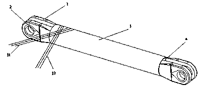
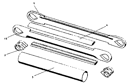
[0052] Such as Figure 1-3 Shown is a bearing rod structure of the present invention. Such as image 3 As shown, the bearing member structure includes:

[0053] Two load-carrying components 1, the two load-carrying components 1 are arranged side by side, wherein, the two ends of each load-carrying component 1 all have an ear part 13 that can be inlaid with a "water drop" type metal bushing 2;

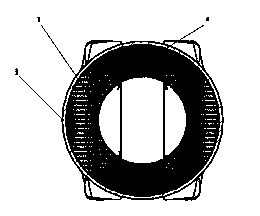
[0054] Two pieces of inner liner 4, the two pieces of inner liner 4 are respectively arranged on the upper part and the lower part of the two pieces of bearing members 1 which are closely arranged, so that the two pieces of bearing members 1 are embedded in the inner liner 4 to form a tubular structure, Such as figure 2 shown; and

[0055] A low-modulus carbon fiber tubular covering layer 3 made by weaving diagonally outside the tubular structure.

[0056] Such as figure 1 Shown is a schematic view of the formation of a bearing rod structure of the present inventi...

Embodiment 2

[0059] Such as Figure 6-8 Shown is the second bearing bar structure of the present invention. Figure 6 It is a schematic diagram of the forming of the bearing rod structure. In this structure, the opposite sides of two load-carrying members 1 are connected and fixed by rivets 5 to form a Figure 7 The cross-sectional structure shown thus simplifies the manufacturing process. Such as Figure 8 As shown, the load-bearing tubular rod for aviation is composed of the following components: two load-bearing components 1, four "drop"-shaped metal bushings 2, several high-strength rivets 5 and special adhesive between metal and resin.

[0060] Such as Figure 9 As shown, although the shape of the molding die is different, its production method is the same as that of the bearing member 1 of Example 1. The only difference is that the high modulus carbon fiber weaving method should take into account that the space of the riveted ear piece should also be filled with high modulus car...

Embodiment 3

[0062] Such as Figure 12-14 Shown is the third bearing bar structure of the present invention. Figure 12 It is a schematic diagram of forming a load-bearing bar structure in Example 3. This structure simplifies the design on the basis of the structure of Example 1, removes the inner liner, and forms such as Figure 13 The section of aeronautical load-bearing tubular member shown. Such as Figure 14 As shown, the load-bearing bar structure includes: two load-bearing members 1, four "droplet"-shaped metal bearings 2, and an outer covering layer 3, which is simpler than the structures of Embodiment 1 and Embodiment 2. Its manufacture method is almost identical with embodiment 1, embodiment 2, only is molding die 11 (see Figure 15 ) is designed to cancel the difference in the mold cavity formed by the shape of the inner liner 4 . The selection and preparation method of carbon fiber is almost the same.

[0063] The manufacturing methods of the above three load-bearing rod ...


PUM

PropertyMeasurementUnit
Outer diameteraaaaaaaaaa
The inside diameter ofaaaaaaaaaa

Abstract

The invention discloses an aerial tube-shaped carbon fiber composite rod piece and a manufacturing method thereof. The rod piece is a tube-shaped structure made from a composite material formed by mixing and weaving high-modulus and low-modulus fibers, wherein the fiber weaving manner is longitudinal arrangement in bearing direction and transverse reinforcement in nonbearing direction. The rod piece comprises two bearing components and metal shaft sleeves, wherein the two bearing components are arranged fixedly, closely adjacently and side by side; the two ends of each bearing component are respectively provided with an ear part; the metal shaft sleeves are embedded in the ear parts; the metal shaft sleeves are in shape of a water drop. According to the rod piece disclosed by the invention, the water-drop-shaped metal shaft sleeves are beneficial to tensile loading and also beneficial to compression-resistance unloading, so that a pull rod can greatly uniformly distribute the load on the carbon fiber composite material when bearing the pressure. The manufacturing method disclosed by the invention is simple and convenient, the provided rod piece has the characteristics of resistance to high-altitude low temperature of -55 DEG C, resistance to ground high temperature of 45 DEG C, resistance to huge tension/pressure of 100 tons, vibration resistance, large torque resistance, no deformation, ultra high rigidity and strength, light dead weight and the like, and the provided rod piece can be taken as key bearing parts on spacecrafts.

Description

technical field [0001] The invention relates to a tubular carbon fiber composite material tubular rod for aviation and a manufacturing method thereof, in particular to manufacture a structural rod with a load capacity of more than 100 tons by utilizing the anisotropic characteristics of the carbon fiber composite material. The composite material structural rod can replace the metal structural rod and be applied in the technical fields of aviation, aerospace, automobile and rail transit, and belongs to the technical field of lightweight composite materials. Background technique [0002] For structural manufacturing technologies in the fields of aviation, aerospace, automobiles, rail transit vehicles, etc., the load-bearing structural parts can adapt to more severe environmental conditions, such as large temperature difference changes between low and high temperatures, vibration, fatigue, etc. , is an urgent need for the development of today's new technologies, especially ligh...

Claims


Application Information

Patent Timeline
IPC IPC(8): B29C70/28B29C70/54B29C70/68B29C71/00B29L23/00
Inventor 莫凡何大海凌璐维尔纳·胡芬巴赫罗萨·克罗尔麦克·古德奥拉夫·赫尔姆斯安德里亚斯·乌尔布莱特奥雷·伦纳马尔科·齐希纳亨里克·安东诺维兹
Owner 莫凡
Why Eureka
Try Eureka