Double-cantilever beam type micro-mechanical acceleration sensor

An acceleration sensor and cantilever beam micro technology, which is applied in the direction of acceleration measurement using inertial force, can solve the problems of low sensitivity, mutual restriction of frequency and sensitivity, and high sensitivity, and achieves good repeatability, simple and symmetrical structure, and good thickness consistency. Effect

Inactive Publication Date: 2013-09-11
INST OF ELECTRONICS ENG CHINA ACAD OF ENG PHYSICS
View PDF4 Cites 4 Cited by
  • Summary
  • Abstract
  • Description
  • Claims
  • Application Information

AI Technical Summary

Problems solved by technology

Cantilever beam micro accelerometers have the problem of mutual restriction between frequency and s

Method used


Image

  • Double-cantilever beam type micro-mechanical acceleration sensor

Examples


Embodiment 1

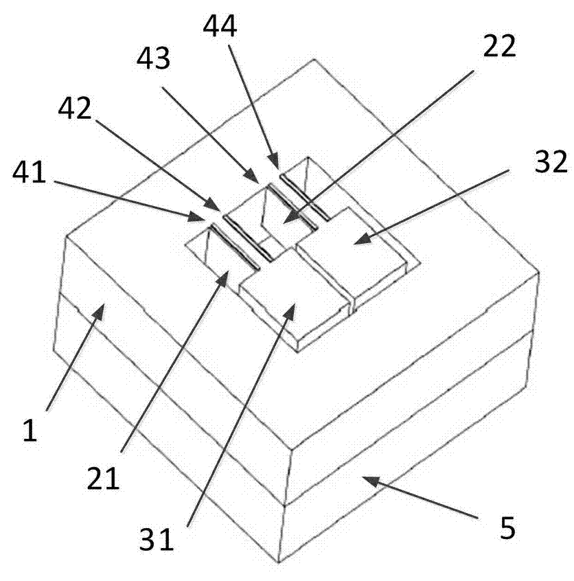
[0023] figure 1 It is a structural schematic diagram of the double cantilever beam type micromachined acceleration sensor of the present invention. exist figure 1 Among them, a kind of double cantilever beam type micromachined acceleration sensor of the present invention comprises a sensitive chip and a lower glass plate 5; wherein, the sensitive chip contains a frame 1, a first cantilever beam 21, a second cantilever beam 22, a first quality block 31, The second mass block 32, the first piezoresistor 41, the second piezoresistor 42, the third piezoresistor 43, and the fourth piezoresistor 44 are connected in such a way that two mutually independent The first cantilever beam 21 and the second cantilever beam 22, one end of the first cantilever beam 21 is connected with the frame 1, the other end is connected with the first mass block 31, one end of the second cantilever beam 22 is connected with the frame 1, and the other end is connected with the frame 1 The second mass blo...

Embodiment 2

[0029] The structure of this embodiment is the same as that of Embodiment 1, except that the thickness of the cantilever beam of the sensitive chip is 100 μm, the length is 130 μm, and the width is 40 μm; the thickness of the proof mass is 100 μm, the length is 120 μm, and the width is 120 μm. The natural frequency is 250kHz, and the sensitivity is about 0.1μV / g / V. The gap between the movable part of the sensitive chip and the glass plate is 200 μm.

[0030] The two mutually independent single-end fixed cantilever beams and mass blocks are placed in opposite directions, that is, the cantilever beams are arranged on opposite sides.

[0031] The present invention is by no means limited to the Examples.


PUM

PropertyMeasurementUnit
Thicknessaaaaaaaaaa
Lengthaaaaaaaaaa
Lengthaaaaaaaaaa

Abstract

The invention provides a double-cantilever beam type micro-mechanical acceleration sensor. The double-cantilever beam type micro-mechanical acceleration sensor is characterized by comprising a sensitive chip and a lower glass plate, wherein the sensitive chip comprises a framework, cantilever beams, a mass block and four piezoresistors; the connection relationships are that the framework is internally provided with two mutually independent cantilever beams, one end of each cantilever beam is connected to the framework while the other end thereof is connected to the mass block, one end of each cantilever beam is connected to the framework while the other end thereof is connected to the mass bock, and the cantilever beams and the mass block compose a movable part of the sensitive chip; the piezoresistors are arranged on the upper surfaces of the cantilever beams; the piezoresistors are arranged on the upper surfaces of the cantilever beams; and the sensitive chip is connected to the lower glass plate through bonding. For an occasion where high resonant frequency of the sensor is necessary, the double-cantilever beam type micro-mechanical acceleration sensor can increase the sensitivity of the sensor by nearly one time, and avoids uncoordinated contradiction in a conventional design.

Description

technical field [0001] The invention belongs to the technical field of micro-acceleration sensors, and in particular relates to a double-cantilever-beam type micro-mechanical acceleration sensor. Background technique [0002] The basic working principle of the micromechanical piezoresistive acceleration sensor is based on the piezoresistive effect of the semiconductor. The beam island structure is commonly used. The mass is supported by the cantilever beam or the connecting beam, and the piezoresistor is fabricated on the beam by ion implantation or diffusion process. When the sensor feels the force, the mass shifts, causing the cantilever beam or connecting beam to twist or bend, and the stress changes in the resistance, which causes the resistance value of the piezoresistor to change. Use appropriate peripheral circuits to convert this change into measurable signals such as voltage, current and other forms of output. After calibration, the relationship between the output ...

Claims


Application Information

Patent Timeline
IPC IPC(8): G01P15/12
Inventor 孙远程袁明权张茜梅王海青武蕊屈明山
Owner INST OF ELECTRONICS ENG CHINA ACAD OF ENG PHYSICS
Why Eureka
Try Eureka